micro sample cell

A kind of sample pool and trace technology, which is applied to measurement devices, material analysis by optical means, instruments, etc., can solve the problems of inaccuracy of sample detection, increase the difficulty of cleaning, etc., to prevent detachment, small accommodating space, and easy disassembly. and cleaning effect

Active Publication Date: 2017-11-21
INST OF PHYSICS - CHINESE ACAD OF SCI
View PDF11 Cites 0 Cited by
  • Summary
  • Abstract
  • Description
  • Claims
  • Application Information

AI Technical Summary

Problems solved by technology

[0003] During optical testing of a flowing sample (such as a biological sample that is easily damaged by light) using the micro sample cell 10, a large number of noise signals will be detected, resulting in inaccurate sample detection
In addition, since the double-sided adhesive 3 cannot be reused, the double-sided adhesive 3 needs to be removed in the process of cleaning the micro sample cell 10, which increases the difficulty of cleaning.

Method used


Image

  • micro sample cell
  • micro sample cell
  • micro sample cell

Examples


Embodiment Construction

[0027] In order to make the object, technical solution and advantages of the present invention clearer, the present invention will be further described in detail below through specific embodiments in conjunction with the accompanying drawings.

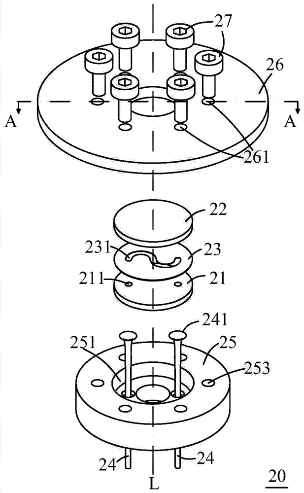
[0028] figure 2 is an exploded view of the micro sample cell according to the first embodiment of the present invention. Such as figure 2 As shown, the micro sample cell 20 includes a glass plate 21 , a glass plate 22 , a guide plate 23 , a guide tube 24 , a holding member 25 and a fixed cover 26 .

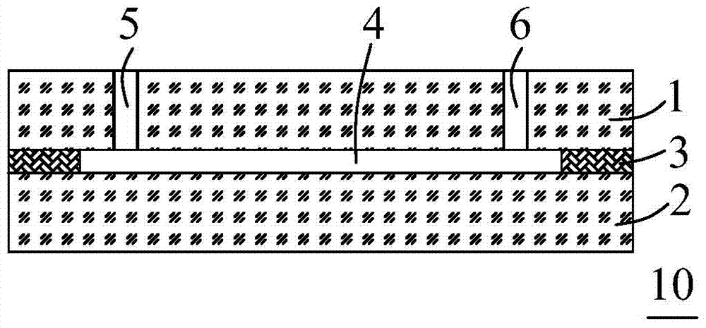
[0029] The glass plates 21, 22 are light-transmitting glass sheets with smooth surfaces made of calcium fluoride. There are two through holes 211 on the glass plate 21 . The deflector 23 located in the middle of the glass plates 21, 22 is a thin sheet made of polytetrafluoroethylene with a thickness of about 100 microns. The two smooth surfaces of the guide sheet 23 can make it closely adhere to the glass plates 21 , 22 . The guide ...


PUM

PropertyMeasurementUnit
thicknessaaaaaaaaaa
widthaaaaaaaaaa

Abstract

The invention provides a micro-sample cell which comprises a first transparent plate, a second transparent plate, a flow deflector located between the first transparent plate and the second transparent plate, an accommodating piece, two flow guide tubes and a fixed cover which is oppositely arranged to the second transparent plate, wherein the first transparent plate is provided with two first through holes; the flow deflector is provided with a flow guide channel, two ends of the flow guide channel are communicated with the two first through holes; the accommodating piece is provided with a groove for accommodating the first transparent plate, the flow deflector and the second transparent plate and is further provided with two second through holes which are communicated with the groove and correspond to the two first through holes; the two flow guide tubes are located in the two second through holes; the fixed cover is detachably and fixedly connected with the accommodating piece. The micro-sample cell is suitable for performing optical measurement on micro-samples and avoids or reduces signal noise caused by sample turbulence.

Description

technical field [0001] The invention relates to an optical measuring device, in particular to a sample pool. Background technique [0002] The sample cell is a very practical device for measuring the optical properties of liquids, figure 1 A sectional view of a micro sample cell in the prior art is shown. The micro-sample cell 10 includes a glass piece 1 and a glass piece 2 arranged opposite to each other. The edges of the glass piece 1 and the glass piece 2 are bonded together by double-sided adhesive 3 and define an accommodating space 4 for accommodating samples. The glass slide 1 has a sampling hole 5 and a sampling hole 6 communicating with the accommodating space 4 . Different thicknesses of double-sided adhesive tape 3 can be selected to adjust the size of the accommodation space 4 , for example, when it is necessary to perform optical measurement on a micro sample, a thinner double-sided adhesive tape 3 can be selected. [0003] During optical testing of a flowing...

Claims


Application Information

Patent Timeline
Patent Type & Authority Patents(China)
IPC IPC(8): G01N21/03G01N21/05
Inventor 朱刚贝李运良李得勇翁羽翔
Owner INST OF PHYSICS - CHINESE ACAD OF SCI
Why Eureka
Try Eureka