
Rotating detonation engine experimental device

An experimental device and engine technology, applied in the field of engine research, can solve the problems of non-adjustable, low quality of fuel and oxygen mixing, unreasonable placement of sensors, etc., and achieve the effect of uniform mixing

Active Publication Date: 2017-10-10
BEIJING INSTITUTE OF TECHNOLOGYGY
View PDF8 Cites 0 Cited by
  • Summary
  • Abstract
  • Description
  • Claims
  • Application Information

AI Technical Summary

Problems solved by technology

[0004] The purpose of the present invention is to provide a rotary detonation engine experimental device in order to solve the problems of unreasonable sensor placement, low fuel and oxygen mixing quality and non-adjustable problems in the existing related experimental technology

Method used


Image

  • Rotating detonation engine experimental device
  • Rotating detonation engine experimental device
  • Rotating detonation engine experimental device

Examples


Embodiment 1

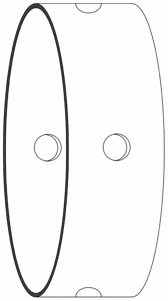
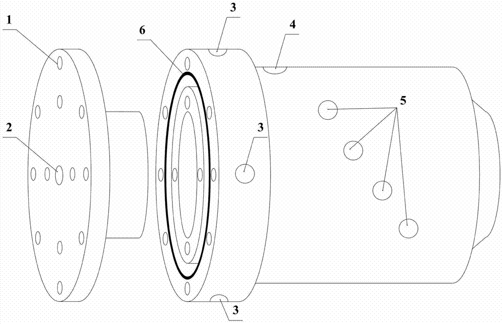
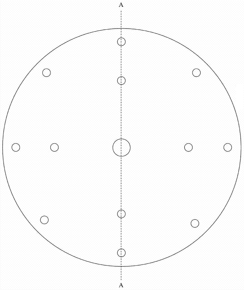
[0031] Rotary detonation engine experimental device, including end cover, outer wall, inner cavity and fuel input control ring 6; screw holes 1, oxygen input port 2 are distributed on the end cover; screw holes 1, fuel input port 3 are distributed on the outer wall, ignition Placement port 4, sensor placement port 5; screw holes 1 are distributed on the inner cavity, oxygen is at the entrance 7 of the annular combustion chamber, and fuel is at the entrance 8 of the annular combustion chamber; through holes are distributed on the fuel input control ring;

[0032] Connection relationship:

[0033] The end cover is a cylindrical body with steps, and there are screw holes 1 and oxygen input port 2 distributed on the end cover;

[0034] The outer wall is a hollow cylinder, with a boss on the outside of the bottom end of the cylinder, and a groove on the inside of the bottom end; the outer wall is distributed with screw holes 1, fuel input port 3, igniter placement port 4, sensor pl...


PUM


Abstract

The invention relates to a rotating detonation engine experimental device, which belongs to the field of engine research. Including end cover, outer wall, inner cavity and fuel input control ring; screw holes and oxygen input port are distributed on the end cover; screw holes, fuel input port, igniter placement port and sensor placement port are distributed on the outer wall; There are screw holes, the oxygen is at the entrance of the annular combustion chamber, and the fuel is at the entrance of the annular combustion chamber; through holes are distributed on the fuel input control ring; in the rotary detonation engine experimental device of the present invention, the diameter of the oxygen at the entrance of the annular combustion chamber is 1mm , the number reaches one hundred; it can make the fuel and oxygen mix more evenly, and increase the possibility of continuous rotating detonation in the annular pipeline.

Description

technical field [0001] The invention relates to a rotating detonation engine experimental device, which belongs to the field of engine research. Background technique [0002] The rotary detonation engine is a new type of detonation engine. Since the detonation wave exists in the annular combustion chamber for a long time and is always in motion, there is no need for high-speed incoming flow and non-stop ignition, and there is no noise induced by the detonation outlet. The detonation wave in the annular combustion chamber continuously rotates and propagates along the circumferential direction, and the high-pressure detonation products expand rapidly and are discharged at high speed in the axial direction, thereby generating propulsion. Therefore, in terms of propulsion, the rotary detonation engine has some advantages of the pulse detonation engine and the stationary detonation engine at the same time, namely: zero start, low noise, low pollution of detonation products, high...

Claims


Application Information

Patent Timeline
Patent Type & Authority Patents(China)
IPC IPC(8): G01M15/00
Inventor 王成胡斌斌宋清官毕湧赵永耀
Owner BEIJING INSTITUTE OF TECHNOLOGYGY
Learn More