
High-rise structure floor slab shock absorption structure releasing multi-direction freedom degrees

A degree of freedom and multi-directional technology, applied in the direction of building structure, floor, shockproof, etc., can solve problems such as suspension cable application, large stress, severe shock feeling of people on the floor, etc., to reduce additional load, increase use space, The effect of improving the degree of utilization

Inactive Publication Date: 2015-07-22
TONGJI UNIV
View PDF3 Cites 9 Cited by
  • Summary
  • Abstract
  • Description
  • Claims
  • Application Information

AI Technical Summary

Problems solved by technology

The technical solution disclosed in the above patent can only release degrees of freedom in one direction. Since the earthquake direction position is often superimposed in multiple directions, this shock absorption method has relatively large limitations and must release degrees of freedom in multiple directions.
At the same time, the roller bearing in this patent has no additional structures such as chute between the floor slab and the main structure, which restricts the beating of the floor slab in the vertical direction, and the floor slab is easy to move up and down during the earthquake, which exerts greater stress on the suspension cables , and also caused the people on the floor to feel more violently

Method used


Image

  • High-rise structure floor slab shock absorption structure releasing multi-direction freedom degrees
  • High-rise structure floor slab shock absorption structure releasing multi-direction freedom degrees
  • High-rise structure floor slab shock absorption structure releasing multi-direction freedom degrees

Examples


Embodiment 1

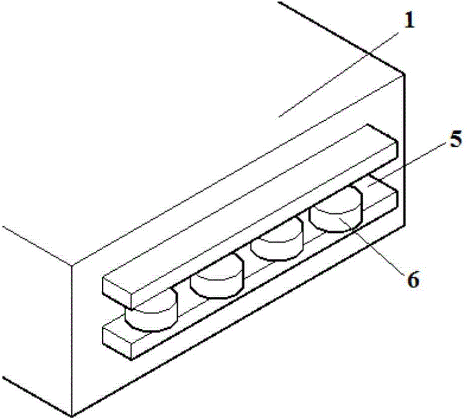
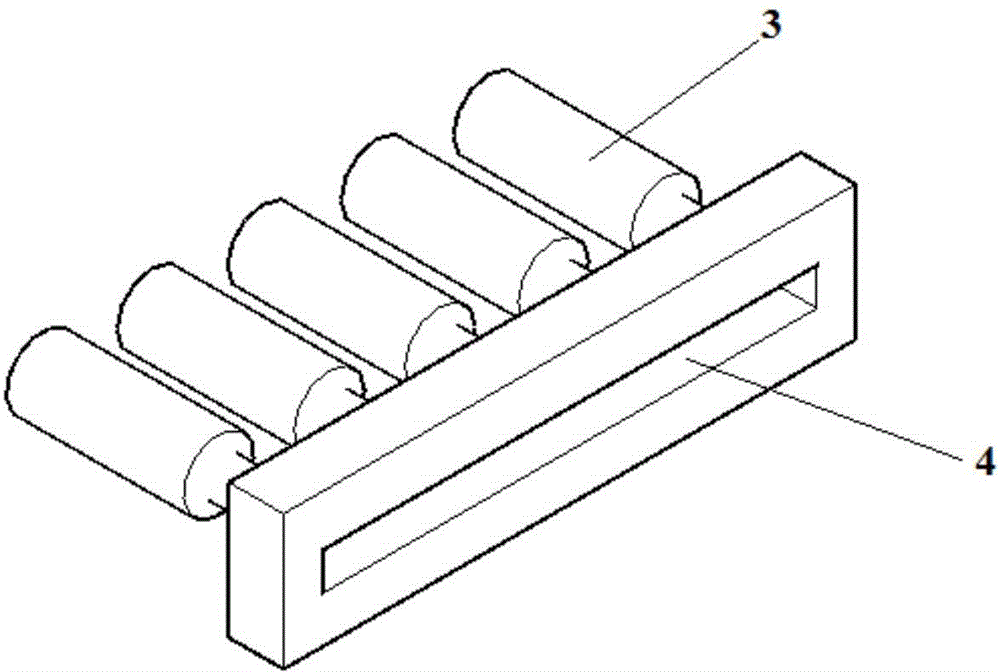
[0031] like Figure 1-3 As shown, a high-rise building floor shock absorbing structure that releases multi-directional degrees of freedom, the floor shock absorbing structure includes a main body stressed frame and a buffer damping mechanism that is arranged in the main body stressed frame and exerts a tuning effect on the main body stressed frame, The main force-bearing frame includes a ground plate, a shear wall 2 vertically arranged on the ground plate, and a rigid beam set on the top of the shear wall 2. 1 around the elastic buffer unit, the floor panel 1 can be relatively slidably connected to the shear wall 2 through the elastic buffer unit;

[0032] During an earthquake, the elastic buffer unit causes relative sliding between the floor slab 1 and the shear wall 2 , realizing the release of the multi-directional freedom of the floor slab 1 .

[0033] The elastic buffer unit includes a plurality of viscous dampers 3 whose bottoms are buried in the shear wall 2, a first r...

Embodiment 2

[0038] In this embodiment, there are 8 viscous dampers 3 in the elastic buffer unit, and the rest are the same as in Embodiment 1.

Embodiment 3

[0040] In this embodiment, there are six viscous dampers 3 in the elastic buffer unit, and the rest are the same as in Embodiment 1.


PUM


Abstract

The invention relates to a high-rise structure floor slab shock absorption structure releasing multi-direction freedom degrees. The floor slab shock absorption structure comprises a body stress frame and a buffering damping mechanism arranged in the body stress frame and applying a tuning function on the body stress frame; the body stress frame comprises a foundation slab, shear walls vertically arranged on the foundation slab and rigid cross beams arranged at the tops of the shear walls, the buffering damping mechanism comprises floor slabs arranged on multiple layers in parallel at equal intervals and elastic buffering units arranged around the floor slabs, and the floor slabs are connected with the shear walls through the elastic buffering units in a sliding mode. Compared with the prior art, the shock absorption structure is simple in structure and compact in layout; as viscous dampers are arranged in the four directions of the body stress frame, and rolling wheels are arranged in the four directions of the floor slab, the multi-direction freedom degrees of the floor slabs can be released, the shock absorption effect is excellent, and the shock absorption structure has excellent application prospects.

Description

technical field [0001] The invention belongs to the technical field of damping devices, and relates to a damping structure for a floor of a high-rise structure, in particular to a damping structure for a floor of a high-rise structure releasing multi-directional degrees of freedom. Background technique [0002] Earthquake is a kind of natural disaster. Earthquake will produce seismic wave, which will cause the building to rise and fall vertically and swing horizontally. When the shear or tensile stress of the building exceeds the ultimate strength of the building, the building will It will break and collapse, causing serious damage. Earthquake disaster is one of the main natural disasters that affect the safety of buildings. [0003] The mega-frame structure is composed of a main structure composed of several large structural units and a substructure composed of other structural units to form a high-rise building structure system with better overall stability and higher eff...

Claims


Application Information

Patent Timeline
Patent Type & Authority Applications(China)
IPC IPC(8): E04B1/98E04B5/02
Inventor 李志远秦子栋张文津张其林
Owner TONGJI UNIV
Learn More