
Device and method for coupling short-cut nitrification with double-SBR denitrifying phosphorus removal

A technology of denitrification and phosphorus removal and short-range nitrification, which is applied in the field of short-range nitrification coupled with double SBR denitrification and phosphorus removal devices, can solve the problems of poor denitrification and phosphorus removal and high energy consumption, so as to increase the amount of sewage treatment, The effect of reducing operating costs and reducing idle rates

Active Publication Date: 2015-07-22
BEIJING UNIV OF TECH
View PDF1 Cites 8 Cited by
  • Summary
  • Abstract
  • Description
  • Claims
  • Application Information

AI Technical Summary

Problems solved by technology

[0006] The present invention aims at the problems of low C / N of domestic sewage, poor nitrogen and phosphorus removal effect of traditional nitrogen and phosphorus removal process, high energy consumption, etc., and couples short-range nitrification and denitrification phosphorus removal technology to realize synchronous depth of nitrogen and phosphorus remove

Method used


Image

  • Device and method for coupling short-cut nitrification with double-SBR denitrifying phosphorus removal
  • Device and method for coupling short-cut nitrification with double-SBR denitrifying phosphorus removal
  • Device and method for coupling short-cut nitrification with double-SBR denitrifying phosphorus removal

Examples


Embodiment Construction

[0027] Embodiments of the present invention will be described in detail below in conjunction with the accompanying drawings and examples.

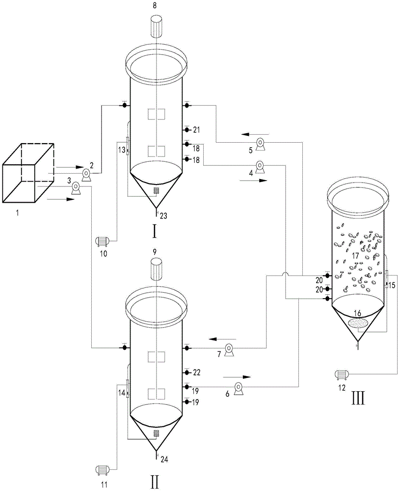
[0028] 1. If figure 1 As shown, the short-range nitrification coupled double SBR denitrification phosphorus removal device mainly includes raw water tank (1), A 2 / O-SBR reactor (I), A 2 / O-SBR reactor (II), N-SBR reactor (III). The main body of the reactor is made of plexiglass, with an effective volume of 15L. Among them, two A 2 The / O-SBR reactors are equipped with agitators and aeration devices, and the bottom is provided with a sludge discharge valve; the N-SBR reactor (III) is equipped with an aeration tray (16) and a biological filler (17), and the biological filler It is cylindrical, made of carbon fiber, with a porosity greater than 95% and a specific surface area of ​​1000-1500m 2 / m 3 ; N-SBR reactor (III) is connected with reflux pump I (5) by N-SBR inlet pump I (4) A 2 / O-SBR reactor (I), connected to return pump II (7...


PUM

PropertyMeasurementUnit
porosityaaaaaaaaaa

Abstract

The invention discloses a device and method for coupling short-cut nitrification with double-SBR denitrifying phosphorus removal, and belongs to the field of biological sewage treatment. The device comprises a raw water tank, two A2 / O-SBR reactors, and an N-SBR reactor. The method comprises the following steps: firstly, raw water enters the A2 / O-SBR reactor I to perform the reaction of anaerobic phosphate release, the reactants stand to generate sediments, and water is discharged into the N-SBR reactor so as to perform short-cut nitrification; after the reaction of the short-cut nitrification ends, the nitrifying liquid flows back to the A2 / O-SBR reactor I so as to perform the reaction of anoxic denitrifying phosphorus removal; after the reaction of anoxic denitrifying phosphorus removal ends, transient aeration is performed so as to further perform aerobic phosphorus uptake and blow off nitrogen; after the reactions end, static settlement and water discharging are performed; after the reaction of the short-cut nitrification in the N-SBR reactor ends, and static settlement and water discharging are finished, the A2 / O-SBR reactor II is started, and because the running manner of the A2 / O-SBR reactor II is the same as that of the A2 / O-SBR reactor I, the vacancy rate of the N-SBR reactor can be lowered. The device and method, which are disclosed by the invention, can save the energy and lower the consumption, and have the advantages that the sludge yield is low, the content of suspended matters in discharged water is low, the technology is simple, the layout is compact, and the device and the method are suitable for processing low-C / N domestic sewage.

Description

technical field [0001] The invention relates to a short-range nitrification coupled double SBR denitrification phosphorus removal device and method, and belongs to the technical field of sewage biological treatment. Background technique [0002] In the traditional biological simultaneous denitrification and phosphorus removal system, biological denitrification and phosphorus removal are respectively completed by the bacteria such as nitrifying bacteria, denitrifying bacteria and phosphorus accumulating bacteria in the sludge. Therefore, the traditional nitrogen and phosphorus removal process There are some flaws. On the one hand, due to the different generation periods of these flora, in order to meet the needs of the generation period of nitrifying bacteria in process design, a longer sludge age is generally adopted, which affects the effect of biological phosphorus removal; on the other hand, denitrification Bacteria and phosphorus-accumulating bacteria compete for carbon...

Claims


Application Information

Patent Timeline
Patent Type & Authority Applications(China)
IPC IPC(8): C02F3/30
Inventor 彭永臻张建华张淼王淑莹程军王聪
Owner BEIJING UNIV OF TECH
Learn More