
Visibility calibration device

A technology for visibility and calibration systems, used in instruments and other directions

Active Publication Date: 2015-07-15
SHENZHEN DARSUN LASER TECH CO LTD
View PDF6 Cites 3 Cited by
  • Summary
  • Abstract
  • Description
  • Claims
  • Application Information

AI Technical Summary

Problems solved by technology

However, how to calibrate the accuracy and reliability of existing visibility measurement equipment or newly developed equipment remains to be solved

Method used


Image

  • Visibility calibration device
  • Visibility calibration device
  • Visibility calibration device

Examples


Embodiment Construction

[0019] In order to make the object, technical solution and advantages of the present invention clearer, the present invention will be further described in detail below in conjunction with the accompanying drawings and embodiments. It should be understood that the specific embodiments described here are only used to explain the present invention, not to limit the present invention.

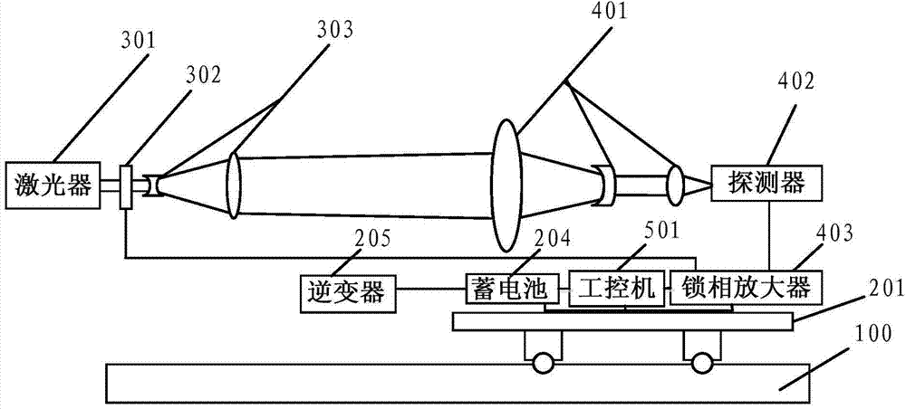
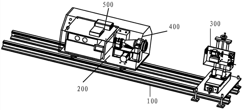
[0020] An embodiment of the present invention provides a visibility calibration system, such as figure 1 , figure 2 with image 3 As shown, it includes: a sliding guide rail device 100, a platform trolley 200, a laser emitting device 300, a photoelectric receiving device 400 and a control and data processing device 500, and the platform trolley 200 is slidably installed on the sliding rail device 100, The platform trolley 200 is provided with a photoelectric receiving device 400 and a control and data processing device 500, and one end of the sliding track device 100 is fixedly provided with a l...


PUM


Abstract

The invention relates to a visibility calibration system. The visibility calibration system comprises a sliding guide rail device, a platform trolley, a laser emitting device, a photoelectric receiving device and a control and data processing device, wherein the platform trolley is slidably arranged on the sliding guide rail device; the photoelectric receiving device and the control and data processing device are arranged on the platform trolley; the laser emitting device is fixedly arranged at one end of the sliding guide rail device; the platform trolley and the photoelectric receiving device are connected with the control and data processing device respectively. According to the system, the precision and the error of a visibility meter can be calibrated.

Description

technical field [0001] The invention relates to the technical field of environmental protection equipment, in particular to a visibility calibration device. Background technique [0002] With the development of the economy, the precise measurement and forecast of various meteorological elements are more and more needed; especially the rapid development of transportation, the increase of various vehicles and the improvement of speed, the demand for visibility measuring instruments in various fields is more urgent . In the field of transportation such as aviation, navigation, highway and port, visibility has an important impact on traffic safety. Taking the aviation field as an example, the accurate measurement of visibility is extremely important to ensure the safe landing and takeoff of aircraft. Weather observations for flight operations are exclusively made at all reporting stations and rapidly changing weather conditions must be frequently reported, especially with rega...

Claims


Application Information

Patent Timeline
IPC IPC(8): G01W1/18
CPCG01W1/18
Inventor 杨少辰孙东松舒志峰徐文静
Owner SHENZHEN DARSUN LASER TECH CO LTD
Learn More