
A kind of mud-water shield host that can be used in upper soft and lower hard formations

A mud-water shield and hard stratum technology, used in mining equipment, earth-moving drilling, tunnels, etc., can solve the problems of difficult stratum settlement control, low driving efficiency, short tool life, etc., to improve construction efficiency and reliability, improve Rock breaking efficiency and the effect of solving cutting problems

Active Publication Date: 2017-01-04
CHINA RAILWAY ENGINEERING EQUIPMENT GROUP CO LTD
View PDF9 Cites 0 Cited by
  • Summary
  • Abstract
  • Description
  • Claims
  • Application Information

AI Technical Summary

Problems solved by technology

[0003] In order to solve the above-mentioned technical problems, the present invention provides a muddy water shield main engine that can be used in upper soft and lower hard strata, which solves the problems of low excavation efficiency, short tool life, and difficulty in stratum settlement control during the construction of upper soft and lower hard strata, reducing Reduce the wear of the cutter and cutter head, prevent the accumulation of rock blocks, and improve the construction efficiency and reliability of the equipment

Method used


Image

  • A kind of mud-water shield host that can be used in upper soft and lower hard formations
  • A kind of mud-water shield host that can be used in upper soft and lower hard formations
  • A kind of mud-water shield host that can be used in upper soft and lower hard formations

Examples


Embodiment 1

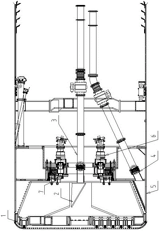
[0021] A muddy water shield main engine that can be used in upper soft and lower hard formations, including a compound cutter head, a main drive and a shield body arranged at the front end, the rear part of the compound cutter head is fixedly connected with the main drive, and the main drive is installed on the shield body. The back of the composite cutter head is provided with a tapered box, the middle part of the shield is provided with a central hopper, and the bottom of the shield is provided with a bottom slurry suction pipe; the rear end of the central hopper is provided with a central slurry suction pipe; the bottom slurry suction pipe The front end is provided with a grille matched with the conical box.

[0022] The composite cutter head cuts the entire soil layer on the face of the front end, and a part of the cut rock and soil enters the central hopper through the composite cutter head, and then is transported to the tail of the shield body through the central slurry ...

Embodiment 2

[0025] A kind of mud-water shield main engine that can be used in upper soft and lower hard formations, such as figure 1 As shown, it includes a compound cutter head 1, a main drive 6 and a shield body 5. The shield body 5 supports the entire device, and the composite cutter head 1 is arranged at the front end of the shield body 5 . The compound cutter head 1 is arranged at the front end of the whole device, and directly contacts with the face of the face. The main drive 6 is installed on the shield body 5, the rear part of the compound cutter head 1 is bolted to the main drive 6 through the flange 7, and the main drive 6 is fixed on the shield body 5 by bolts. The effect of main drive 6 is mainly to drive the rotation of compound cutter head 1 . The main drive 6 can rotate forward and reverse, so that the composite cutterhead 1 has the function of forward and reverse rotation, thereby preventing rock blocks from accumulating on one side of the composite cutterhead 1 and the...

Embodiment 3

[0035]A muddy water shield main engine that can be used in upper soft and lower hard formations, including a compound cutter head, a main drive and a shield body arranged at the front end, the rear part of the compound cutter head is fixedly connected with the main drive, and the main drive is installed on the shield body. The back of the composite cutter head is provided with a tapered box, the middle part of the shield is provided with a central hopper, and the bottom of the shield is provided with a bottom slurry suction pipe; the rear end of the central hopper is provided with a central slurry suction pipe; the bottom slurry suction pipe The front end is provided with a grille matched with the conical box.

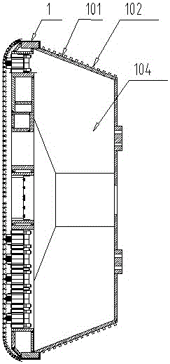
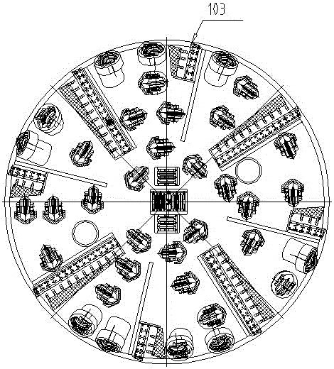
[0036] The conical box body is a whole, and the conical surface is provided with fragment holes, and the two sides of the fragment holes are provided with wear-resistant blocks. The fragment holes are evenly distributed on the conical surface of the conical box, and th...


PUM


Abstract

The invention discloses a slurry shield main engine for upper-soft lower-hard ground. The slurry shield main engine comprises a composite cutter-head, a main driver and a shield body, wherein the composite cutter-head is arranged at the forefront of the slurry shield main engine, the rear part of the composite cutter-head is connected with the main driver in a bolting way, and the main driver is arranged on the shield body; the back of the composite cutter-head is provided with a conical box body, the middle part of the shield body is provided with a central hopper, and the bottom of the shield body is provided with a bottom pulp sucking pipe; the rear end of the central hopper is provided with a central pulp sucking pipe, and the front end of the bottom of pulp sucking pipe is provided with a grid matched with the conical tank body. According to the slurry shield main engine provided by the invention, a tunnel face can be balanced by the pressure of muddy water, rocks can be broken by the excavation of the composite cutter-head and the relative rotation between the conical tank body and a grating plate, residual soil at the lower part of the slurry shield main engine can be lifted to the central hopper by using a scum board and a mucking plate and then can be discharged by the central pulp sucking pipe, so as to realize the function of synchronously discharging residues up and down, and prevent the accumulation of the rocks; furthermore, the problems that the pressure balance of the tunnel face is unlikely to be controlled in the construction of the upper-soft lower-hard ground and the hard rocks at the lower part of the tunnel face are difficult to cut can be effectively solved, and the construction efficiency and reliability of equipment can be improved.

Description

technical field [0001] The invention belongs to the technical field of tunnel construction equipment, and in particular relates to a mud-water shield host machine that can be used in upper soft and lower hard strata. Background technique [0002] Existing shield machines are mainly divided into earth pressure balance shields, mud-water balance shields, open shields, dual-mode shields, etc., which are used for the construction of underground tunnels and are suitable for soft soil, hard rock, and composite strata. However, when constructing on a stratum that is soft at the top and hard at the bottom, it is difficult to construct due to the particularity of the stratum. The lower part of the stratum is hard, and the excavation speed of the shield machine is slow, and the upper part of the softer stratum is easy to excavate, but limited by the lower stratum, repeated cutting of the upper soft soil will cause increased wear of the cutter head and tools, and the ground subsidence ...

Claims


Application Information

Patent Timeline
Patent Type & Authority Patents(China)
IPC IPC(8): E21D9/06
CPCE21D9/06E21D9/0607E21D9/08E21D9/12
Inventor 李建斌肖威
Owner CHINA RAILWAY ENGINEERING EQUIPMENT GROUP CO LTD
Learn More