
Spiral rib stepping device applied to steel bar truss production line

A steel truss and production line technology, applied in the directions of online mesh, wire processing, and other household appliances, can solve the problems of different lengths of steel truss finished products, affecting the stepping accuracy of the truss, affecting the stepping speed, etc. The effect of high precision and elimination of time waste

Active Publication Date: 2015-07-15
TJK MACHINERY TIANJIN
View PDF5 Cites 0 Cited by
  • Summary
  • Abstract
  • Description
  • Claims
  • Application Information

AI Technical Summary

Problems solved by technology

In the prior art, the pressing and releasing action of the continuous reciprocating stepping device not only affects the stepping speed, but also the reaction time of pressing and releasing seriously affects the stepping accuracy of the truss when the stepping speed is high, resulting in The length of the finished steel truss is different, and the length error is large

Method used


Image

  • Spiral rib stepping device applied to steel bar truss production line
  • Spiral rib stepping device applied to steel bar truss production line
  • Spiral rib stepping device applied to steel bar truss production line

Examples


Embodiment Construction

[0027] Embodiments of the present invention will be described below in conjunction with the accompanying drawings.

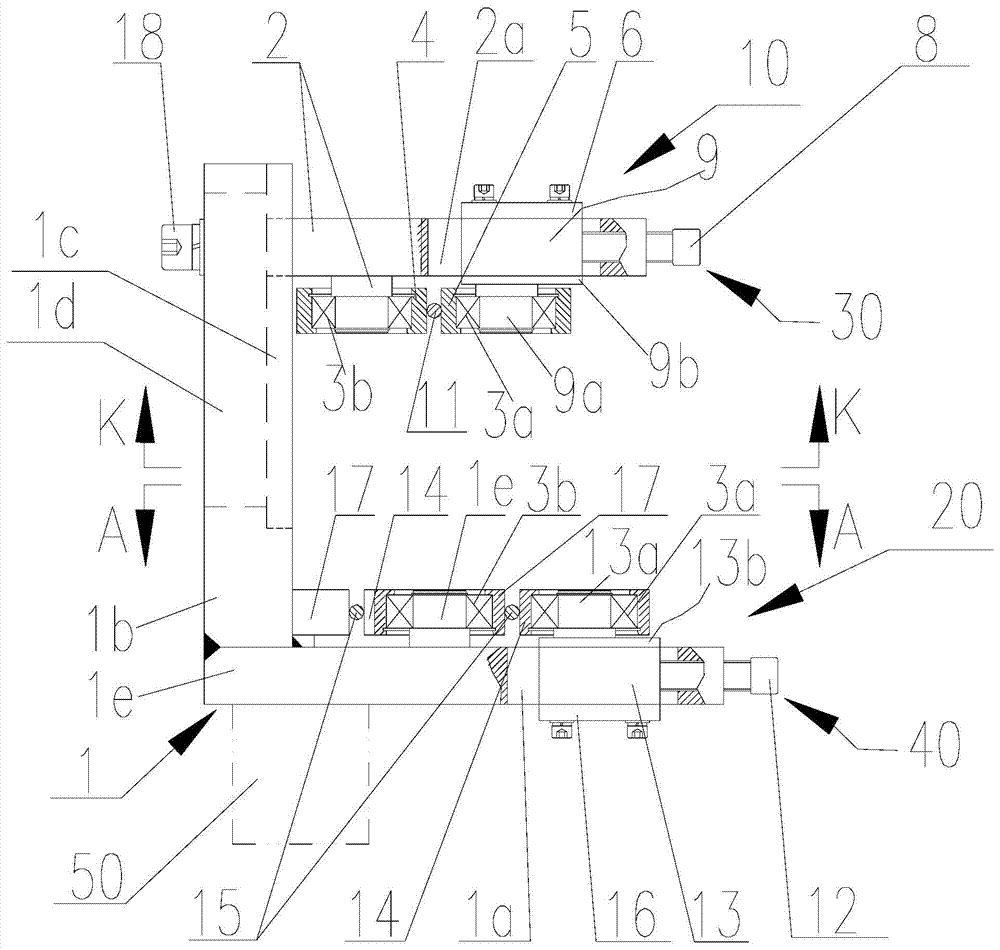
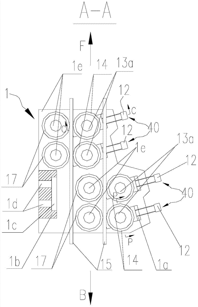
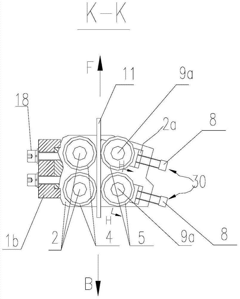
[0028] As shown in the figure, the present invention provides a chord stepping device in a steel bar truss production line. The chord stepping device includes: a stepping frame 1 connected to a reciprocating movement mechanism 50, and the stepping frame 1 is composed of a horizontal frame 1e and The vertical frame 1b is composed of; the horizontal frame 1e is located at the bottom of the stepping frame 1, and the lower pressing part 20 for clamping the lower chord bar 15 is arranged on the horizontal frame 1e; the vertical frame 1b is fixed on the horizontal frame 1e, The upper pressing part 10 for clamping the upper chord bar 11 is arranged on the vertical frame 1b.

[0029] The lower pressing part 20 includes: the lower fixed wheel 17 and the lower movable wheel 14 clamped on both sides of the lower string bar 15; the inner hole of the lower fixed wheel 17 is ...


PUM


Abstract

The invention discloses a spiral rib stepping device applied to a steel bar truss production line. The spiral rib stepping device structurally comprises a lower pressing part and an upper pressing part, wherein the lower pressing part and the upper pressing part are arranged on a stepping frame; the lower pressing part comprises a lower fixed wheel and a lower moving wheel, the lower fixed wheel and the lower moving wheel are clamped on the two sides of a lower spiral rib, a second one-way bearing is mounted on the lower fixed wheel, a first one-way bearing is mounted on the lower moving wheel, and the lower moving wheel is connected with the lower moving seat; the upper pressing part comprises an upper fixed wheel and an upper moving wheel, the upper fixed wheel and the upper moving wheel are clamped on the two sides of the upper spiral rib, a second one-way bearing is mounted on the upper fixed wheel, a first one-way bearing is mounted on the upper moving wheel, and the upper moving wheel is connected with the upper moving seat; the rotation directions of the first one-way bearings and the second one-way bearings are opposite. The spiral rib stepping device applied to the steel bar truss production line has the beneficial effects that the first one-way bearings and the second one-way bearings are opposite in the rotation directions and are respectively mounted on the fixed wheels and the moving wheels, and the fixed wheels and the moving wheels respectively press the upper spiral rib and the lower spiral rib, so that the stepping of the upper spiral rib and the lower spiral rib can be achieved, and no-load reset can be realized. The spiral rib stepping device has the advantages that the stepping speed and the precision are high, the structure is simple, and the adjustment is convenient.

Description

technical field [0001] The invention relates to a steel bar truss production line, in particular to a chord bar stepping device in the steel bar truss production line. Background technique [0002] At present, the commonly used steel truss is a triangular beam truss. In the triangular beam truss production line, the stepping device of one upper chord bar and two lower chord bars is a continuous reciprocating stepping device, that is, when the starting chord bars step, the air cylinder or oil cylinder respectively Compress the string bar, and release the string bar at the end point to retract and reset. In the prior art, the pressing and releasing actions of the continuous reciprocating stepping device not only affect the stepping speed, but also the reaction time of pressing and releasing seriously affects the stepping accuracy of the truss when the stepping speed is high, resulting in The finished steel trusses have different lengths, and the length error is large. Conte...

Claims


Application Information

Patent Timeline
Patent Type & Authority Applications(China)
IPC IPC(8): B21F27/20B21F23/00
Inventor 陈振东
Owner TJK MACHINERY TIANJIN
Learn More