
Configurable wireless smart socket

A smart socket and configuration technology, which is applied to the parts of the connection device, coupling device, program control, etc., can solve the problems of flexibility that cannot meet the flexible application, time-consuming and labor-intensive, single communication mode of the smart socket, etc.

Inactive Publication Date: 2015-07-08
ZHEJIANG SUPCON RES
View PDF6 Cites 4 Cited by
  • Summary
  • Abstract
  • Description
  • Claims
  • Application Information

AI Technical Summary

Problems solved by technology

[0002] At present, there are a variety of wireless smart sockets equipped with microprocessors in the market. These smart sockets equipped with microprocessors have certain intelligent control capabilities, but their flexibility has not yet met the needs of smart buildings, energy-saving control systems, and smart home systems. In systems such as intelligent systems, there is a demand for flexible application of smart sockets. When it is necessary to change the smart control scheme of the socket, it is necessary to rewrite the underlying program based on the microprocessor. This method is time-consuming and laborious, and the application is extremely inflexible; The communication method of the smart socket is relatively simple, and it is not suitable for the application in intelligent systems such as intelligent buildings, energy-saving control systems, and smart home systems with rich and varied functional requirements and flexible communication requirements.

Method used


Image

  • Configurable wireless smart socket
  • Configurable wireless smart socket
  • Configurable wireless smart socket

Examples


Embodiment Construction

[0022] The technical solutions in the embodiments of the present invention will be clearly and completely described and discussed below in conjunction with the accompanying drawings of the present invention. Obviously, what is described here is only a part of the examples of the present invention, not all examples. Based on the present invention All other embodiments obtained by persons of ordinary skill in the art without creative efforts fall within the protection scope of the present invention.

[0023] In order to facilitate the understanding of the embodiments of the present invention, specific embodiments will be taken as examples for further explanation below in conjunction with the accompanying drawings, and each embodiment does not constitute a limitation to the embodiments of the present invention.

[0024] Configuration: "Configure" means "configuration", "setting", "setting", etc. It means that users can complete the software functions they need in a simple way simi...


PUM


Abstract

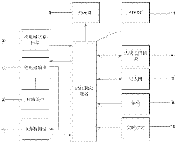
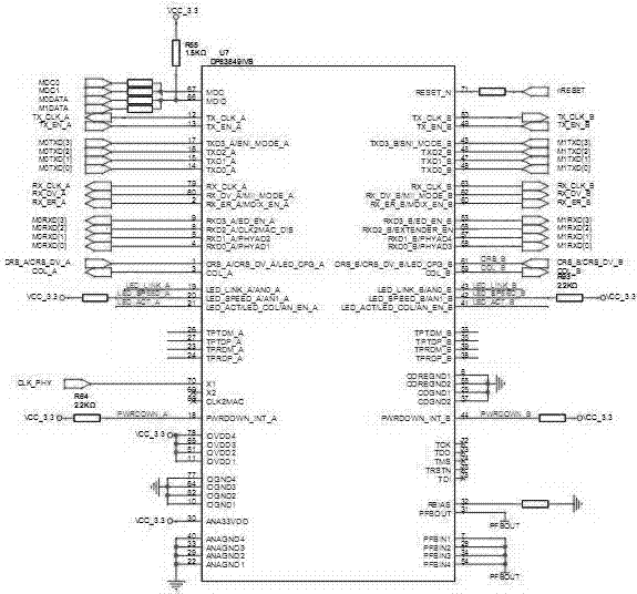
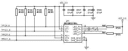
The invention discloses a configurable wireless smart socket. The configurable wireless smart socket comprises a CMC processor, an AC / DC module, a relay output circuit, a photoelectrical coupling circuit, an electrical parameter measuring circuit, a wireless communication circuit, a real-time clock circuit and an Ethernet circuit, wherein the AC / DC module is used for converting alternating currents into direct currents; the relay output circuit is connected with a GPIO pin of the CMC processor; the photoelectrical coupling circuit is arranged at the output end of the relay output circuit and used for reexamining the state of a relay, and a generated reexamining signal is input to the CMC processor through the GPIO pin; the electrical parameter measuring circuit is connected with the CMC processor and used for current sampling and voltage sampling; the wireless communication circuit is connected with the CMC processor and used for bidirectional data communication; the real-time clock circuit is connected with the CMC processor and used for providing time information; the Ethernet circuit is connected with the CMC processor and used for configuration or communication with the outside.

Description

technical field [0001] The invention relates to the field of electrical equipment, in particular to a configurable wireless intelligent socket. Background technique [0002] At present, there are a variety of wireless smart sockets equipped with microprocessors in the market. These smart sockets equipped with microprocessors have certain intelligent control capabilities, but their flexibility has not yet met the needs of smart buildings, energy-saving control systems, and smart home systems. In systems such as intelligent systems, there is a demand for flexible application of smart sockets. When it is necessary to change the smart control scheme of the socket, it is necessary to rewrite the underlying program based on the microprocessor. This method is time-consuming and laborious, and the application is extremely inflexible; The communication method of the smart socket is relatively simple, and it is not suitable for the application in intelligent systems such as intellig...

Claims


Application Information

Patent Timeline
Patent Type & Authority Applications(China)
IPC IPC(8): H01R13/66G05B19/042
Inventor 谢灿华程涛张燕俞志群崔凤勇袁延波
Owner ZHEJIANG SUPCON RES
Learn More