
A transmission mechanism of leakage reclosing circuit breaker

A technology of transmission mechanism and circuit breaker, which is applied in the direction of protection switch operation/release mechanism, etc. It can solve the problems of large torque of the transmission rod, reduce the service life of the transmission mechanism, and easy deformation and damage of the transmission gear, so as to achieve good separation effect and prolong the service life , Reduce the effect of motor transmission torque

Active Publication Date: 2017-10-20
XIAMEN HONGFA ELECTRICAL SAFETY & CONTROLS CO LTD
View PDF6 Cites 0 Cited by
  • Summary
  • Abstract
  • Description
  • Claims
  • Application Information

AI Technical Summary

Problems solved by technology

[0005] The reclosing device of the molded case circuit breaker of the two kinds of circuit breakers solves the technical problem of the synchronous rotation of the electric closing mechanism and the manual closing mechanism. However, its defect is that the transmission rod connected with the circuit breaker operating mechanism is directly installed On the gear, the torque generated by the transmission rod to the transmission gear is relatively large, the transmission gear is easily deformed and damaged, and the service life of the transmission mechanism is reduced; at the same time, when the transmission rod is driven, the meshing between the gear and the gear is completed, and the meshing rotation between the gears is easy to wear , further reducing the service life

Method used


Image

  • A transmission mechanism of leakage reclosing circuit breaker
  • A transmission mechanism of leakage reclosing circuit breaker
  • A transmission mechanism of leakage reclosing circuit breaker

Examples


Embodiment Construction

[0034] The present invention will be described in detail below in conjunction with the accompanying drawings and specific embodiments.

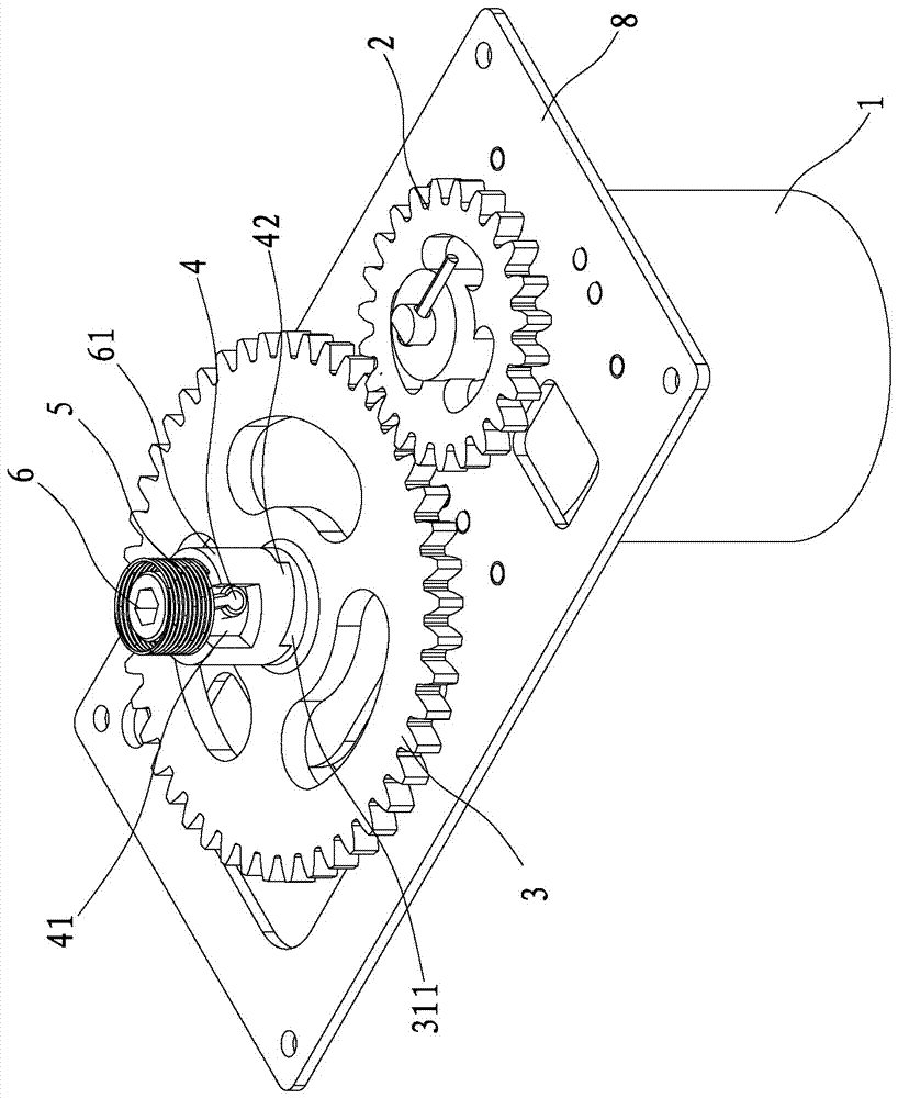
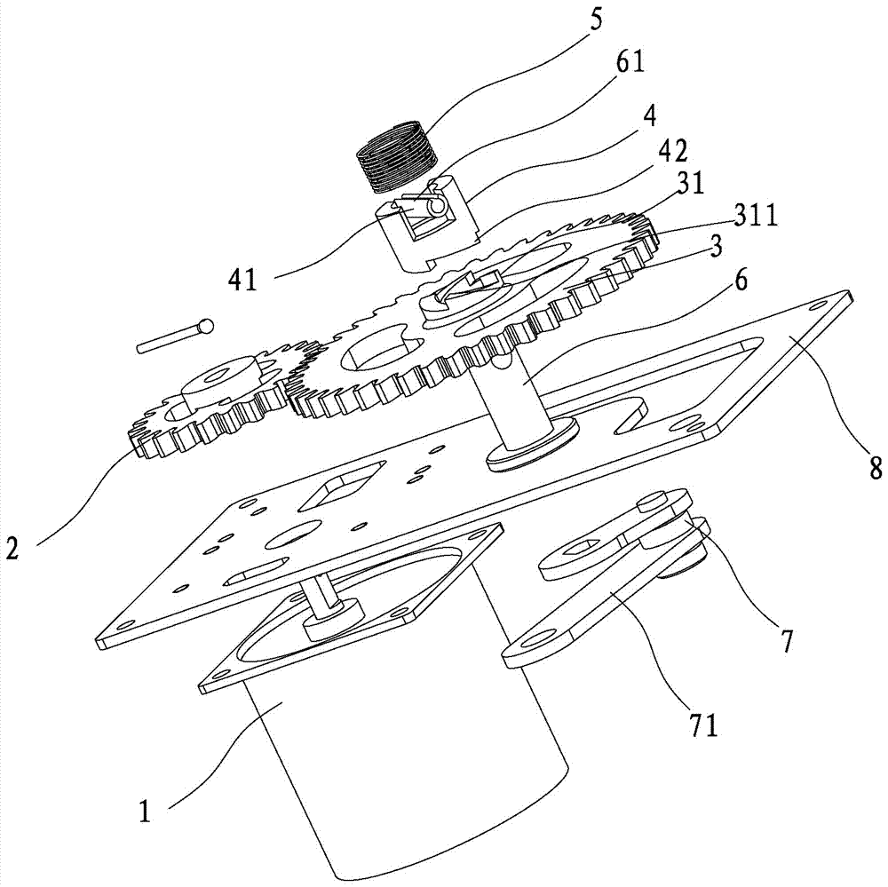
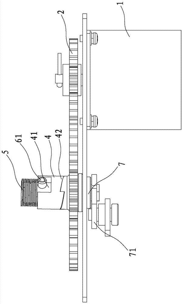
[0035] refer to Figure 1 to Figure 5 As shown, the transmission mechanism of a leakage reclosing circuit breaker disclosed by the present invention includes a motor 1, a first transmission gear 2, a second transmission gear 3, a first ratchet 31, a second ratchet 4, a compression spring 5, and a rotating shaft 6 And shaft sleeve 7.

[0036] Wherein, the motor 1, the first transmission gear 2 and the second transmission gear 3 form an electric drive mechanism.

[0037] The motor 1 is arranged on the mounting plate 8 , the mounting plate 8 is fixed in the circuit breaker housing, the first transmission gear 2 is arranged on the output shaft of the motor 1 , and the first transmission gear 2 rotates synchronously with the output shaft of the motor 1 . The output shaft of the first transmission gear 2 and the motor 1 can be connected by a pin ...


PUM


Abstract

The invention discloses a transmission mechanism for an electric leakage reclosing circuit breaker. The transmission mechanism comprises an electric drive mechanism, a first ratchet wheel, a second ratchet wheel, a compression spring, a rotating shaft and a shaft sleeve. The electric drive mechanism is arranged on an installation plate. The installation plate is fixed in a circuit breaker shell. The electric drive mechanism drives the first ratchet wheel. One side of the rotating shaft is rotationally sleeved with the first ratchet wheel. The rotating shaft is rotationally arranged on the installation plate. The rotating shaft is rotationally sleeved with the second ratchet wheel which is located above the first ratchet wheel. The second ratchet wheel is in linkage with the rotating shaft. The rotating shaft is sleeved with the compression spring for providing pressure for the second ratchet wheel. Under the effect of the compression spring, ratchets of the first ratchet wheel and ratchets of the second ratchet wheel are meshed; the shaft sleeve is installed on the other side, penetrating through the installation plate, of the rotating shaft, and a driving rod is installed on the shaft sleeve and connected with a circuit breaker operation mechanism. The rotating shaft and the driving rod are connected by means of the shaft sleeve, the driving rod can be driven with small torque, and the service life of the transmission mechanism is prolonged.

Description

technical field [0001] The invention relates to the technical field of circuit breakers, in particular to a transmission mechanism of an electric leakage reclosing circuit breaker. Background technique [0002] In the prior art, the reclosing device of the molded case circuit breaker includes two control modes: electric closing mechanism and manual closing mechanism. The resistance of closing is reduced, and the external force pushing the motor to rotate will damage the motor. [0003] In order to solve the above problems, the publication number is CN 203192626U, which discloses a double clutch mechanism of a reclosing circuit breaker, including a manual closing device and an electric closing device, the manual closing device and the electric closing device are connected in linkage, and the electric closing device Linked with the transmission rod, the electric closing device includes a first gear, a clutch ring, a clutch lever, a transmission plate, and a motor. The first g...

Claims


Application Information

Patent Timeline
Patent Type & Authority Patents(China)
IPC IPC(8): H01H71/10H01H71/70
CPCH01H71/10H01H71/70
Inventor 林观锏卓江海林耀国
Owner XIAMEN HONGFA ELECTRICAL SAFETY & CONTROLS CO LTD
Learn More