Polarity-reversal compensation method, device and liquid crystal display
A technology of polarity inversion and compensation method, applied in static indicators, instruments, etc., can solve the problems of affecting the display effect, different brightness, low charging rate, etc., to avoid bright lines and dark lines, and improve the display effect.
- Summary
- Abstract
- Description
- Claims
- Application Information
AI Technical Summary
Problems solved by technology
Method used
Image

Examples
Embodiment 1
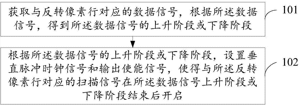
[0025] see figure 1 , the polarity reversal compensation method provided by the embodiment of the present invention includes:
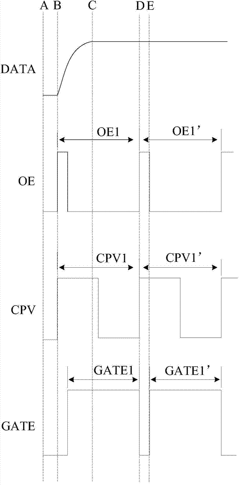
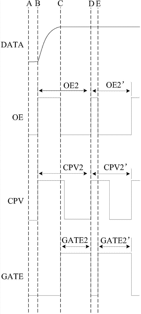
[0026] Step 101, obtain the data signal corresponding to the inverted pixel row, and obtain the rising phase or falling phase of the data signal according to the data signal; wherein, the data signal is used to charge the pixel, and N rows of inversion need to occur in the pixel When inverting, the data signal also changes accordingly, so that the pixel is charged with a current of the opposite polarity to that before the inversion. For example: inverting the pixel row needs to be reversed from positive polarity to negative polarity, and the data signal is changed from high level to low level; or, inverting the pixel row needs to be reversed from negative polarity to positive polarity, and the data signal is changed from low level goes high. Such as figure 2 , image 3 As shown, DATA is a data signal, and in the B-C stage, inverting the pixel row...
Embodiment 2
[0033] Since the scanning signal is turned on after the rising phase or falling phase of the data signal, the inversion period of the vertical pulse clock signal is the same as the inversion period of the output enable signal, and the non-inversion period of the vertical pulse clock signal is the same as that of the output enable signal. The non-inversion period is the same, therefore, both the inversion period and the non-inversion period of the vertical pulse clock signal need to be calculated and adjusted, such as Figure 4 As shown, the compensation method for polarity reversal provided by the above embodiment also includes:
[0034] Step 103, obtain the duration T1 of one frame, the number N of the reversed pixel rows in one frame, the number H1 of the pixel rows in the display area, the number H2 of the pixel rows in the blank area, and the data The duration of the rising or falling phase of the signal is T2.
[0035] Step 104, according to the T1, N, H1, H2 and T2, cal...
Embodiment 3
[0039] In the embodiment of the present invention, the specific method for calculating the inversion period and the non-inversion period of the vertical pulse clock signal in step 104 in the second embodiment will be described in detail, please refer to Figure 5 , Step 104 in Embodiment 2 can also be refined into Step 1041-Step 1043, including:
[0040] Step 1041, use the formula n=[H1 / N] to calculate the number of inversion times n; wherein, H1 is the number of pixel rows in the display area, the inversion pixel rows exist in the display area, and N is an inversion in one frame The number of inversion pixel rows, the number of inversion times in one frame can be calculated from the formula in this step.
[0041] Step 1042, using the formula T C =(T1-n*T2) / (H1+H2), calculate the non-inversion period T of the vertical pulse clock signal C ; T1 is the duration of one frame, T2 is the duration of the rising phase or falling phase of the data signal, and T1-n*T2 is calculated t...
PUM
 Abstract
Description
Claims
Application Information
 - Generate Ideas
- Intellectual Property
- Life Sciences
- Materials
- Tech Scout
- Unparalleled Data Quality
- Higher Quality Content
- 60% Fewer Hallucinations
Browse by: Latest US Patents, China's latest patents, Technical Efficacy Thesaurus, Application Domain, Technology Topic, Popular Technical Reports.
© 2025 PatSnap. All rights reserved.Legal|Privacy policy|Modern Slavery Act Transparency Statement|Sitemap|About US| Contact US: help@patsnap.com