Tail end instrument for single port laparoscopy minimally invasive surgery flexible robot with multiple freedom degrees
A minimally invasive surgery and robot technology, applied in the field of surgical robots, can solve the problems of too simple parts of the instrument, low overall integration, and large overall size, so as to reduce the number of wounds, enhance operability and precision, and reduce pain. Effect
- Summary
- Abstract
- Description
- Claims
- Application Information
AI Technical Summary
Problems solved by technology
Method used
Image
Examples
specific Embodiment approach 1
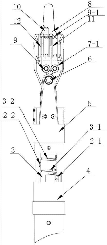
[0016] Specific implementation mode one: combine Figure 1-Figure 4 Describe this embodiment, the robot of this embodiment comprises pivot rotation rod 3, pivot rotation fixed rod 4, wrist threading bucket 5, wrist shaft 6, first clamping tongs guide wheel 7, the first clamping tongs joint 8. The second clamp guide wheel 9, the second clamp joint 10 and the wrist joint 13,
[0017] One end of the flexible arm is affixed to one end of the pivoting fixed rod 4, the other end of the pivoting fixed rod 4 is rotationally connected to the pivoting rotating rod 3, and the other end of the pivoting rotating rod 3 is fixedly connected to the wrist threading barrel 5 , the wrist shaft 6 passes through a pair of connecting ears of the wrist threading barrel 5, one end of the wrist joint 13 is mounted on the wrist shaft 6, and the other end of the wrist joint 13 is equipped with a first clamp joint 8 and a second clamp Hold forceps joint 10;
[0018] The drive wire of the fourth joint p...
specific Embodiment approach 2
[0026] Specific implementation mode two: combination figure 1 and image 3 Describe this embodiment, the wrist threading bucket 5 of this embodiment is made into one by base 5-1 and two connecting ears 5-2, and base 5-1 is provided with first guide wheel fixing column 5-3, second Guide wheel fixed column 5-4, the 3rd guide wheel fixed column 5-5 and the 4th guide wheel fixed column 5-6, the inwall of the first guide wheel fixed column 5-3 is provided with two guide wheels one, the second The inwall of guide wheel fixed column 5-4 is provided with a guide wheel two, and the sidewall of the second guide fixed column 5-4 is provided with two guide wheels five, and the inwall of the 3rd guide wheel fixed column 5-5 is provided with Two guide wheels three, are provided with a guide wheel four on the inwall of the 4th guide wheel fixed column 5-6, are provided with two guide wheel six on the sidewall of the 4th guide wheel fixed column 5-6, the first guide wheel The height of fixe...
specific Embodiment approach 3
[0027] Specific embodiment three: the pivoting rotating rod 3 of this embodiment, the pivoting fixed rod 4, the threading barrel 5 at the end, the first clamping forceps joint 9, and the second clamping forceps joint 10 are all made of 1Cr18Ni9 material. Advantages of the above-mentioned structure All the above-mentioned parts need to be in contact with human tissue, and the use of such materials meets the requirements of the human body for materials. Other implementation manners are the same as the specific implementation manner 1.
[0028] Working principle: the fourth motor drives the wire through the fourth joint to realize the axial rotation of the wrist pivot joint, the fifth motor drives the wire through the fifth joint to realize the pitching motion of the wrist joint, and the sixth motor passes through the sixth joint The driving wire realizes the opening and closing movement of the first clamping forceps joint, and the seventh motor realizes the opening and closing m...
PUM
 Abstract
Description
Claims
Application Information
 - R&D
- Intellectual Property
- Life Sciences
- Materials
- Tech Scout
- Unparalleled Data Quality
- Higher Quality Content
- 60% Fewer Hallucinations
Browse by: Latest US Patents, China's latest patents, Technical Efficacy Thesaurus, Application Domain, Technology Topic, Popular Technical Reports.
© 2025 PatSnap. All rights reserved.Legal|Privacy policy|Modern Slavery Act Transparency Statement|Sitemap|About US| Contact US: help@patsnap.com


