
Mobile station apparatus, base station apparatus, communication method and integrated circuit

A communication method and technology of a mobile station, which are applied in the directions of wireless communication, separation device of transmission path, signaling distribution, etc., can solve problems such as hindering the transmission efficiency of base stations and terminals, and inability to efficiently notify control information, etc.

Active Publication Date: 2015-07-01
SHARP KK
View PDF3 Cites 5 Cited by
  • Summary
  • Abstract
  • Description
  • Claims
  • Application Information

AI Technical Summary

Problems solved by technology

[0013] However, in a heterogeneous network configuration and / or a CoMP transmission scheme, etc., when an existing method is used as a notification method for notifying control information to a terminal from a base station, a problem arises in the capacity of the control information notification area.
As a result, the control information for the terminal cannot be efficiently notified from the base station, which is a key factor that hinders the improvement of the transmission efficiency in the communication between the base station and the terminal.

Method used


Image

  • Mobile station apparatus, base station apparatus, communication method and integrated circuit
  • Mobile station apparatus, base station apparatus, communication method and integrated circuit
  • Mobile station apparatus, base station apparatus, communication method and integrated circuit

Examples


no. 1 approach

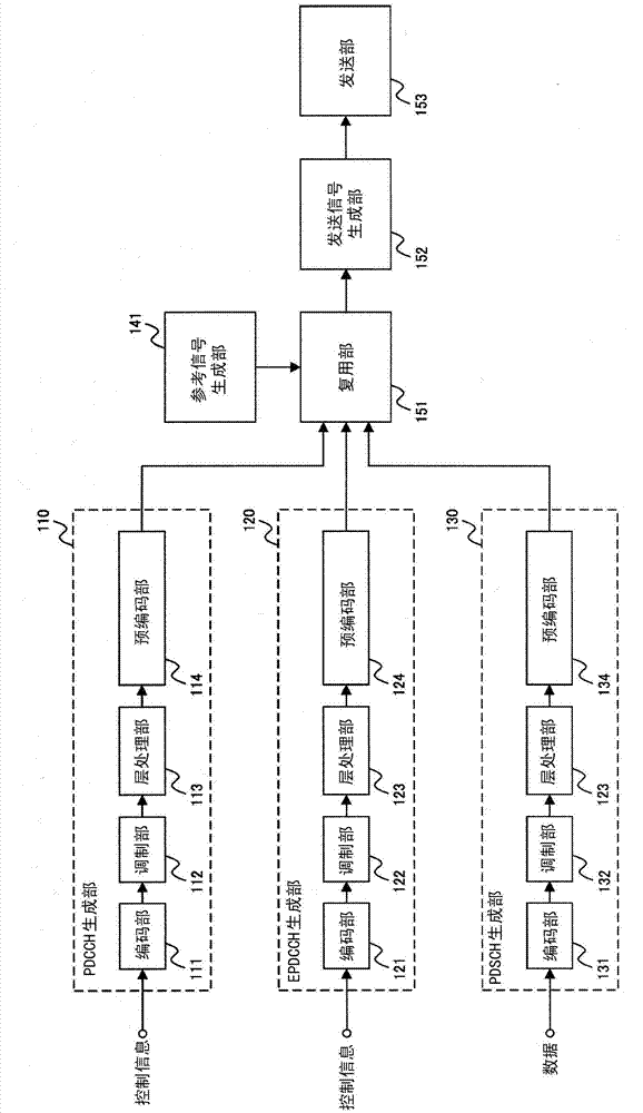
[0056] Embodiments of the present invention will be described below. The communication system in this embodiment includes a base station and terminals. Here, the base station may be a transmission device, a cell, a transmission point, a transmission antenna group, a transmission antenna port group, a component carrier, or an eNodeB. In addition, the base station includes a macro cell, a pico cell, a femto cell, a small cell, an RRH (Remote Radio Head), distributed antennas, and the like. A terminal may be a terminal device, a mobile terminal, a receiving point, a receiving terminal, a receiving device, a receiving antenna group, a receiving antenna port group, or UE (User Equipment). In addition, a terminal can identify a base station (transmission point) based on a parameter specific to a cell or a parameter specific to the terminal. For example, a terminal can identify a base station (transmission point) based on a cell ID, which is a cell-specific identifier, parameters (...

no. 2 approach

[0227] Embodiments of the present invention will be described below. The communication system in this embodiment includes the base station and the terminal described in the first embodiment. Hereinafter, differences from the first embodiment will be described.

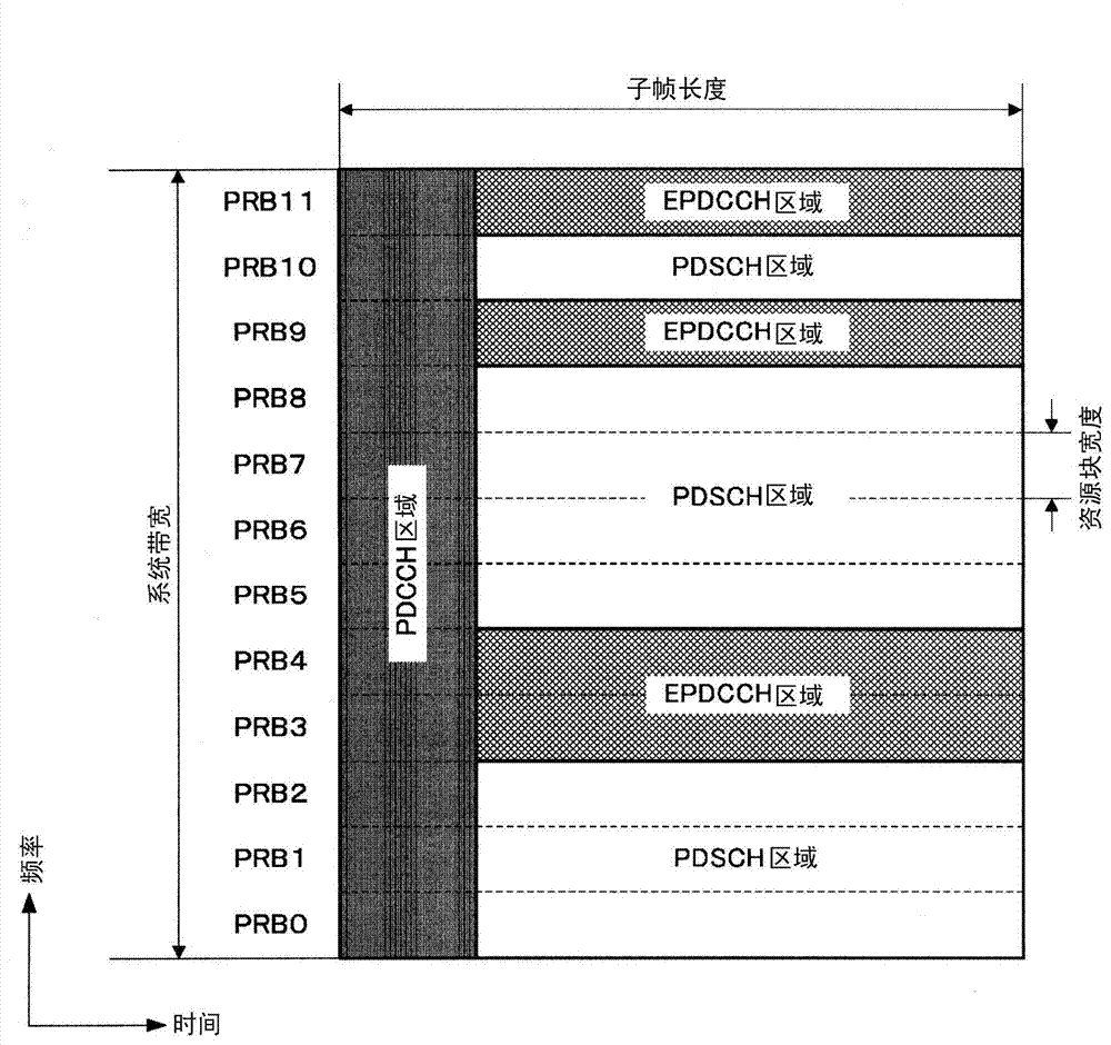
[0228] In the first embodiment, when two EPDCCH sets are configured, the combination of EPDCCH candidates is as follows Figure 8-11 As in the example shown, based on the number N of RB pairs constituting the first EPDCCH set and the second EPDCCH set 1 and N 2 , and conditions for each EPDCCH set of the first EPDCCH set and the second EPDCCH set are independently specified. That is, each EPDCCH set of the first EPDCCH set and the second EPDCCH set has four states based on the first condition or the second condition. Specifically, the first state is that the first EPDCCH set is in the first condition, and the second EPDCCH set is in the first condition. The second state is that the first EPDCCH set is in th...


PUM


Abstract

The purpose of the present invention is, in a wireless communication system in which a base station and a terminal communicate, to allow the base station to efficiently report control information for the terminal. A base station device maps an EDPCCH to any EDPCCH candidate included in each of a first EDPCCH set and a second EDPCCH set which are set by RRC signaling, whereupon a mobile station device monitors the EDPCCH candidate. The EDPCCH candidate is determined, in one of physical resource block pairs that are set for EDPCCH transmission in the first EDPCCH set, at least on the basis of the numbers of resource elements satisfying a predetermined standard.

Description

technical field [0001] The present invention relates to base station, terminal, communication system, communication method and integrated circuit. Background technique [0002] WCDMA (registered trademark) (Wideband Code Division Multiple Access; Wideband Code Division Multiple Access), LTE (Long Term Evolution; Long Term Evolution), LTE- Wireless communication systems such as A (LTE-Advanced (advanced)) or IEEE (The Institute of Electrical and Electronics engineers; Institute of Electrical and Electronics Engineers) based Wireless LAN, WiMAX (Worldwide Interoperability for Microwave Access; Worldwide Interoperability for Microwave Access) Among them, a base station (cell, transmitting station, transmitting device, eNodeB) and a terminal (mobile terminal, receiving station, mobile station, receiving device, UE (User Equipment; User Equipment)) each have a plurality of transmitting and receiving antennas, and by using MIMO (Multi Input Multi Output (multiple input multiple o...

Claims


Application Information

Patent Timeline
Patent Type & Authority Applications(China)
IPC IPC(8): H04W72/04
CPCH04L5/0094H04L5/0053H04W72/0406H04W72/04H04W72/20H04L5/0035H04L5/0007H04W72/23
Inventor 示泽寿之野上智造铃木翔一今村公彦
Owner SHARP KK
Learn More