Monitoring equipment and display interface layout adjustment method and device thereof
A layout adjustment and display interface technology, which is applied in special data processing applications, instruments, electrical digital data processing, etc., can solve the problems of many operation steps, unintuitive operation, inconvenient operation, etc., and achieve the reduction of operation steps, intuitive and simple operation , Improve the effect of user experience
- Summary
- Abstract
- Description
- Claims
- Application Information
AI Technical Summary
Problems solved by technology
Method used
Image
Examples
Embodiment 1
[0058] In this embodiment, the exchange of layout display elements is taken as an example for illustration.
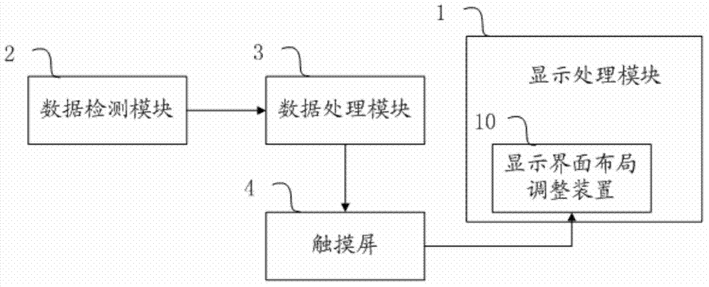
[0059] In this embodiment, the layout adjustment gesture is a layout display element exchange gesture, and the structural diagram of the layout adjustment unit is as follows Figure 4 It includes an original display area determination subunit 131 , a target display area determination subunit 132 , an exchange judgment subunit 133 and an exchange subunit 134 . The original display area determination subunit 131 is used to determine the original display area based on the user's touch operation, and the display elements in the original display area are used as objects to be exchanged; the target display area determination subunit 132 is used to determine the target display area based on the user's touch operation , using the display element in the target display area as the target object; the interchange judgment subunit 133 is used to judge whether the object to be excha...
Embodiment 2
[0080] In another concrete example, please refer to Image 6 , the layout adjustment unit includes an original display area determination subunit 131 , a target display area determination subunit 132 , an exchange judgment subunit 133 , an exchange subunit 134 and a second prompt subunit 136 . After determining the original display area, the exchange judgment subunit 133 identifies the first display area that allows the object to be exchanged to be displayed in all other display areas except the original display area on the display interface according to the vital sign data item corresponding to the object to be exchanged. Class display area and the second class display area that does not allow the display of the object to be exchanged; the second prompt subunit 136 is used to perform different identifications on the first class display area and the second class display area according to the recognition result output by the interchange judgment subunit highlight.
[0081] Bas...
Embodiment 3
[0092] The difference between this embodiment and the above embodiment is that the layout adjustment unit further includes a dragging subunit, which is used to display the corresponding icon of the original display area near the original display area after the original display area is determined. Or change the display mode of the interface object in the original display area, and then move the corresponding icon or interface object in the original display area along the track of the user's touch operation according to the touch operation input by the user through the touch screen. The interface object refers to an interface control used to display vital sign data items in the interface display area. The action recognition unit is also used to detect the user's touch operation and generate touch track information, which at least includes the position information of each contact point in the touch track; the target display area determination subunit is used to obtain the touch tr...
PUM
 Abstract
Description
Claims
Application Information
 - R&D
- Intellectual Property
- Life Sciences
- Materials
- Tech Scout
- Unparalleled Data Quality
- Higher Quality Content
- 60% Fewer Hallucinations
Browse by: Latest US Patents, China's latest patents, Technical Efficacy Thesaurus, Application Domain, Technology Topic, Popular Technical Reports.
© 2025 PatSnap. All rights reserved.Legal|Privacy policy|Modern Slavery Act Transparency Statement|Sitemap|About US| Contact US: help@patsnap.com


