Differential transformer type displacement sensor
A differential transformer type, displacement sensor technology, applied in the field of sensors, can solve the problems of low accuracy and poor linearity of differential transformer type displacement sensors, and achieves increased linear travel, improved linearity and output accuracy, and improved magnetic field distribution. Effect
- Summary
- Abstract
- Description
- Claims
- Application Information
AI Technical Summary
Problems solved by technology
Method used
Image
Examples
Embodiment 1
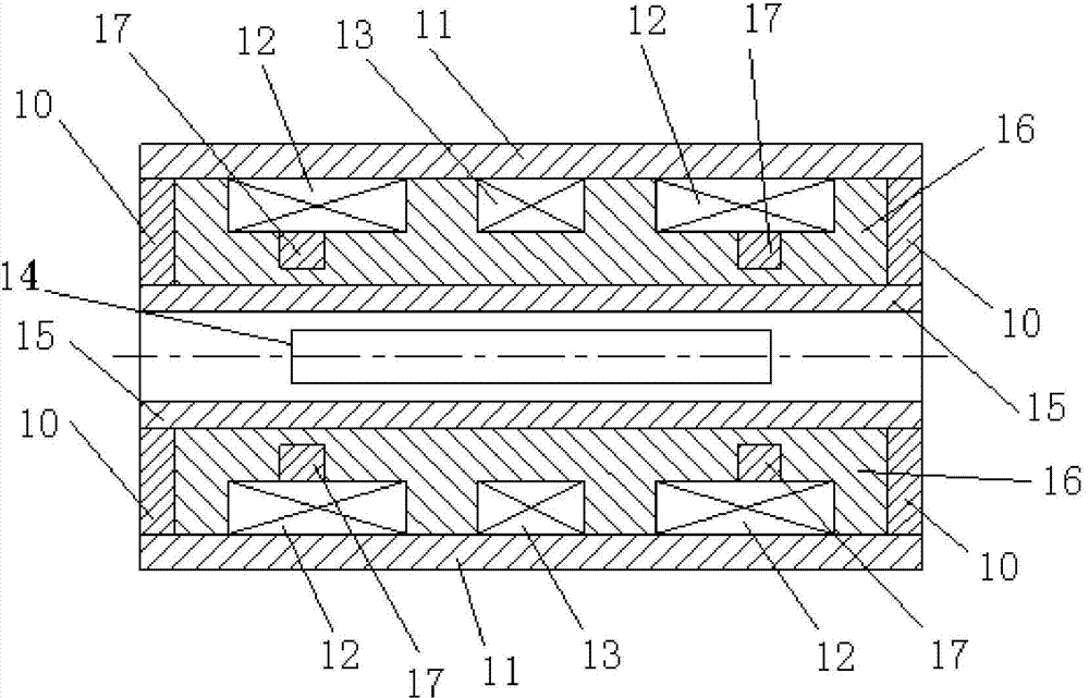
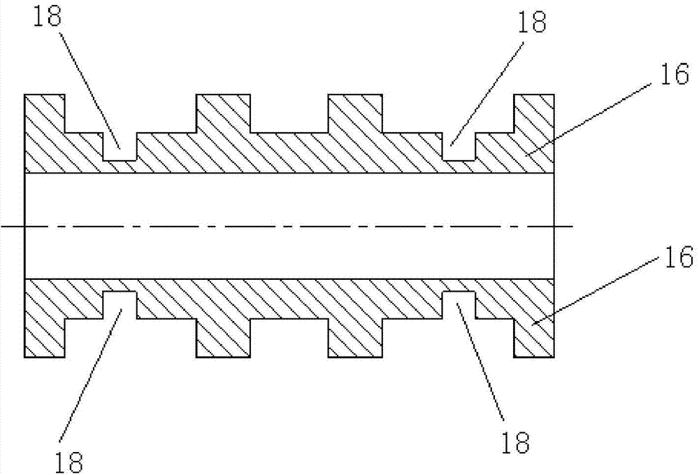
[0038] Such as figure 2 with image 3 As shown, the differential transformer displacement sensor of this embodiment includes a skeleton 16 , an annular end cover 10 , a casing 11 , an iron core 14 , two secondary coils 12 , a primary coil 13 , a pressure-resistant tube 15 and a magnetically permeable ring 17 . The skeleton 16 is a cylindrical structure, the outer wall of the skeleton 16 is provided with a primary coil groove and two secondary coil grooves, and the two secondary coil grooves are symmetrically arranged on both sides of the primary coil groove, and the primary coil 13 is wound around The secondary coil 12 is disposed in the groove of the primary coil, and the secondary coil 12 is wound in the groove of the secondary coil. The shell 11 is sheathed on the framework 16 , and both ends of the framework 16 are provided with ring-shaped end caps 10 . The iron core 14 is located in the inner cavity of the skeleton 16 . The skeleton 16 is provided with an annular gro...
Embodiment 2
[0040] Such as Figure 4 with Figure 5 As shown, the differential transformer type displacement sensor of this embodiment includes an annular end cover 20 , a casing 21 , an iron core 24 , two secondary coils 22 , three primary coils 23 , a skeleton 25 and a magnetically permeable ring 26 . The skeleton 25 is a cylindrical structure, the secondary coil 22 and the primary coil 23 are wound on the skeleton 25 , and the secondary coil 22 is located between two adjacent primary coils 23 . The casing 21 is sheathed on the frame 25 and covers the primary coil 23 and the secondary coil 22 , and both ends of the frame 16 are provided with ring-shaped end caps 20 . The iron core 24 is located in the inner cavity of the skeleton 25 . An annular groove 27 is provided on the outer wall of the skeleton 25 , the annular groove 27 is coaxial with the skeleton 25 , and the magnetically conductive ring 26 is installed in the annular groove 27 . Wherein, the number of the annular slots 27 i...
Embodiment 3
[0042] Such as Image 6 with Figure 7 As shown, the differential transformer displacement sensor of this embodiment includes an annular end cover 30 , an iron core 34 , a primary coil 32 , two secondary coils 33 , a casing 31 , a frame 35 and a magnetically permeable ring 36 . The skeleton 35 is a cylindrical structure, the primary coil 32 is wound on the skeleton 35, the secondary coil 33 is wound on the outer periphery of the primary coil 32, the shell 31 is sleeved on the skeleton 35, and covers the primary coil 32 and the secondary coil 33, and both ends of the framework 35 are provided with ring-shaped end caps 30. The iron core 34 is located in the inner cavity of the skeleton 35 . The outer wall of the skeleton 35 is provided with an annular groove 37 , which is coaxial with the skeleton 35 , and the magnetically conductive ring 36 is installed in the annular groove 37 . As shown in the figure, the number of annular grooves 37 is two.
PUM
 Abstract
Description
Claims
Application Information
 - R&D
- Intellectual Property
- Life Sciences
- Materials
- Tech Scout
- Unparalleled Data Quality
- Higher Quality Content
- 60% Fewer Hallucinations
Browse by: Latest US Patents, China's latest patents, Technical Efficacy Thesaurus, Application Domain, Technology Topic, Popular Technical Reports.
© 2025 PatSnap. All rights reserved.Legal|Privacy policy|Modern Slavery Act Transparency Statement|Sitemap|About US| Contact US: help@patsnap.com


