Rolling-cut transverse shearing device

A rolling-cutting and cross-cutting technology, which is applied in the direction of shearing devices, shearing machine accessories, shearing machine equipment, etc., can solve the problem of short shearing length, inability to realize thin plate and strip cross-cutting, cut-to-length segmentation, shearing, etc. Cutting and other problems, to achieve the effect of reducing wear, simple and reasonable structure, and convenient operation

Active Publication Date: 2015-07-01
JINTIAN COPPER GROUP CORP NINGBO
View PDF11 Cites 2 Cited by
  • Summary
  • Abstract
  • Description
  • Claims
  • Application Information

AI Technical Summary

Problems solved by technology

An eccentric shaft is set in the above-mentioned shearing device, although it can realize continuous shearing, it can only be vertical shearing, and it is only suitable for edge trimming or crushing shearing of thick plates and strips, and cannot realize horizontal shearing of thin plates and strips. Cutting and cut-to-length segmented cutting, there is a problem that the cutting length is slightly shorter than the set length

Method used


Image

  • Rolling-cut transverse shearing device
  • Rolling-cut transverse shearing device
  • Rolling-cut transverse shearing device

Examples


Embodiment Construction

[0028] The present invention will be further described in detail below in conjunction with the accompanying drawings and embodiments.

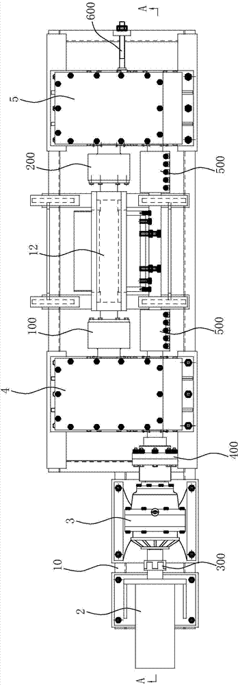
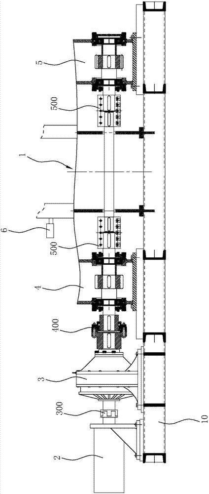
[0029] Such as Figure 1~6 As shown, the roll-cutting type cross-shearing device of this embodiment is applied in the shearing process of plate and strip materials. The rails 900 are connected, and the discharge end is connected with the discharge rail 800 . The rolling shearing device in this embodiment includes a frame 10 , an upper and lower shearing mechanism 1 and a drive assembly connected to the upper and lower shearing mechanism 1 . The driving assembly in the present embodiment includes servo motor 2, cycloid reducer 3, first gearbox 4 and second gearbox 5, the output shaft of servo motor 2 is connected with cycloid reducer 3 through a quincunx coupling 300 The input shaft transmission connection, the input end of the first gearbox 4, the second gearbox 5 is connected with the output shaft transmission of the cycloid reducer 3 throu...


PUM


Abstract

The invention relates to a rolling-cut transverse shearing device which comprises a vertical shearing mechanism and a drive assembly connected with the vertical shearing mechanism in a driving mode. The vertical shearing mechanism comprises a support, an upper transmission roller, a lower transmission roller, an upper shearing blade arranged on the upper transmission roller, and a lower shearing blade arranged on the lower transmission roller. The upper transmission roller and the lower transmission roller are arranged on the upper part and the lower part of the support respectively. The lower shearing blade is horizontally arranged on the top of the lower transmission roller. The upper shearing blade is arranged at the bottom of the upper transmission roller. The included angle between the blade edge of the upper shearing blade and the axis of the upper transmission roller ranges from 1.5 degrees to 3 degrees. A measurement roller which can measure the conveying speed and the length of a plate strip and provided with an encoder is arranged on the portion, close to the feed end, of the vertical shearing mechanism. The cutting depths of the upper shearing blade and the lower shearing blade can be consistent, it is ensured that the maximum shearing force value can reach 20 T, the accuracy of the size of a notch of the plate strip is improved, the upper shearing blade does not horizontally slide, abrasion to the shearing blades can be effectively reduced, the service life of the shearing blades can be prolonged, bending deformation on the fracture surface of the plate strip can be avoided, and the shearing quality can be improved.

Description

technical field [0001] The invention relates to the technical field of shearing equipment for metal plates and strips, in particular to a roll-cut cross-shear device used on a plate and strip shearing line. Background technique [0002] The transverse shearing device is one of the main equipments on the plate and strip finishing line. It is used to cut the coiled strip into a certain length of plate according to the requirements after being flattened (such as cutting the head, cutting the tail, cutting the length ). At present, the more commonly used transverse shearing device is the servo parallel shearing machine, its two cutting blades are parallel to each other, and the cutting is realized by the up and down movement of the upper cutting blade or the rising of the lower cutting blade, which can withstand the maximum Shear force. In the actual production process, the cutting dimensional accuracy of the above-mentioned servo parallel shearing machine and the quality of t...

Claims


Application Information

Patent Timeline
Patent Type & Authority Applications(China)
IPC IPC(8): B23D15/12B23D33/00
Inventor 李国华代文钢汪雄风温霄何黎明刘聪
Owner JINTIAN COPPER GROUP CORP NINGBO
Why Eureka
Try Eureka