Prefiltering in mimo receiver

A receiver, pre-filter technology, applied in the direction of shaping network, space transmit diversity, channel estimation, etc. in the transmitter/receiver, can solve the problem of not guaranteeing the minimum phase channel Givens rotation and so on

Inactive Publication Date: 2015-06-24
TELEFON AB LM ERICSSON (PUBL)
View PDF3 Cites 5 Cited by
  • Summary
  • Abstract
  • Description
  • Claims
  • Application Information

AI Technical Summary

Problems solved by technology

However, polynomial QR decomposition as done by Foster et al. is based on Givens rotation which does not guarantee the minimum phase channel after prefiltering

Method used


Image

  • Prefiltering in mimo receiver
  • Prefiltering in mimo receiver
  • Prefiltering in mimo receiver

Examples


Embodiment Construction

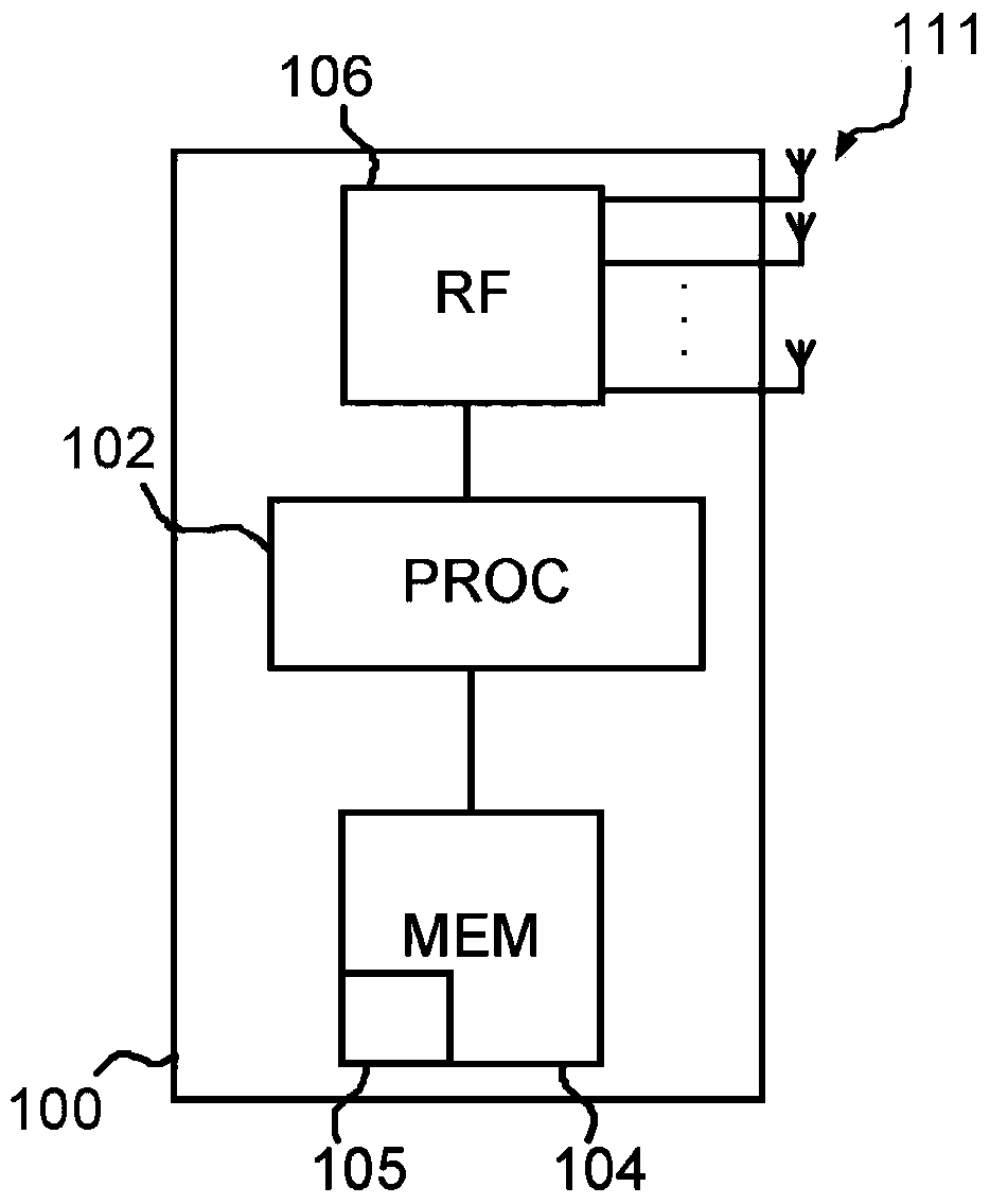
[0061] figure 1 A MIMO enabled mobile communication terminal 100 is schematically illustrated comprising a processor 102 , memory 104 , radio frequency RF receive and transmit circuitry 106 and a plurality of antenna elements 111 . Radio communication via antenna 111 is achieved through RF circuitry 106 controlled by processor 102 as will be understood by the skilled person. The processor 102 uses software instructions 105 stored in the memory 104 in order to control all functions of the terminal 100, including the functions of the receiver circuit in the RF circuit 106 described in detail below with respect to demodulation. In other words, at least the RF circuitry 106, the processor 102 and the memory 104 form part of the control and communication circuitry which is configured to control demodulation as outlined above and described in detail below. Further details on how these units operate in order to perform normal functions within a mobile radio communication system are...


PUM


Abstract

Data signals transmitted by a plurality of transmitting antennas over a radio channel are demodulated. The method comprises receiving (202) on a plurality of receiving antennas, a data signal and a reference signal, the contents of the reference signal being known a priori to the receiver. The contents of the reference signal are used for calculating (204) an estimated polynomial channel matrix. A polynomial pre-filter matrix is calculated (206, 208) by a decomposition of the estimated polynomial channel matrix into a product of a paraunitary polynomial matrix and an upper triangular polynomial matrix with minimum phase filters on its main diagonal, where the polynomial pre-filter matrix is obtained by calculating the paraconjugate of the paraunitary polynomial matrix. The received data signal is demodulated (212) where the received data signal is multiplied with the calculated polynomial pre-filter matrix.

Description

technical field [0001] The field of the disclosure is controlling a multiple-input multiple-output MIMO receiver. In particular, calculations associated with determining the characteristics of a radio channel between a transmitter and a MIMO receiver in order to improve performance when demodulating received signals. Background technique [0002] In a mobile wireless communication system using Multi-User MIMO (MU-MIMO), several users are scheduled to transmit simultaneously during the same time and frequency interval. These users can be distinguished by assigning to them different and preferably orthogonal reference signals so that all channels from all transmit antennas to all receive antennas can be estimated. Reference signals (or training sequences) are sequences known to the receiver, and they are transmitted together with the user signal so that the receiver can estimate the distortion of the received signal after its transmission. [0003] MU-MIMO forms part of, for...

Claims


Application Information

Patent Timeline
Patent Type & Authority Applications(China)
IPC IPC(8): H04B7/04H04B7/08
CPCH04B7/06H04B7/08H04L25/0204H04L25/0228H04L25/0242H04L25/0246H04L25/03891H04B7/0413H04L2025/03426H04L25/03H04B1/40
Inventor H·萨林M·洛佩兹
Owner TELEFON AB LM ERICSSON (PUBL)
Why Eureka
Try Eureka