
Image Correction Device Image Correction Method and Recording Medium

A technology in images and images, applied in image communication, image enhancement, image analysis, etc., can solve problems such as points that do not directly reflect three-dimensional deformation, and cannot correct deformation with high precision

Active Publication Date: 2018-06-15
CASIO COMPUTER CO LTD
View PDF8 Cites 0 Cited by
  • Summary
  • Abstract
  • Description
  • Claims
  • Application Information

AI Technical Summary

Problems solved by technology

[0006] However, in the above-mentioned technique, the intersection points of the aforesaid plurality of vertical lines and the plurality of horizontal lines are set according to specific criteria determined according to the presupposed deformation state of the original, and do not directly reflect the three-dimensionality of each part of the original. deformed point
Therefore, when there is a local deformation in the original that is not assumed, there is a problem that the deformation in this part cannot be corrected with high precision.

Method used


Image

  • Image Correction Device Image Correction Method and Recording Medium
  • Image Correction Device Image Correction Method and Recording Medium
  • Image Correction Device Image Correction Method and Recording Medium

Examples


Embodiment approach 1

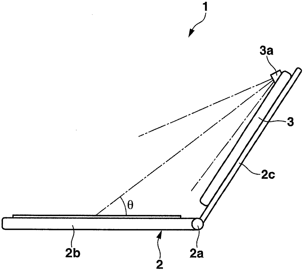
[0025] First, Embodiment 1 of the present invention will be described. figure 1 It is an external view of the image correction device 1 common to Embodiment 1 and Embodiment 2 described later.

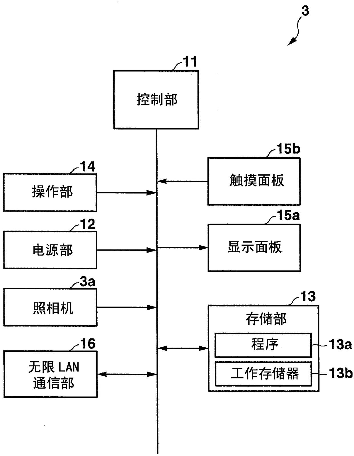
[0026] The image correction device 1 mainly includes: a frame body 2 composed of a first frame body 2b and a second frame body 2c that can be opened and closed via a hinge portion (connecting portion) 2a; The main body of the device 3.

[0027] The frame body 2 can be fixed into the first frame body 2b and the second frame body 2c to figure 1 The illustrated use state is opened at a predetermined angle. In this use state, the first frame body 2 b is used as a document holder for placing an arbitrary document (deformable predetermined object). Examples of originals include various books, notebooks, books, and printed matter based on them.

[0028] The device main body 3 is an information processing device including a camera 3a for photographing a document placed on the first housing ...

Embodiment approach 2

[0128] Next, Embodiment 2 of the present invention will be described. This embodiment has figure 1 as well as figure 2 In addition, when correcting a document image, the control unit 11 performs image correction processing, which is different from the first embodiment and will be described later, based on a program stored in the storage unit 13 .

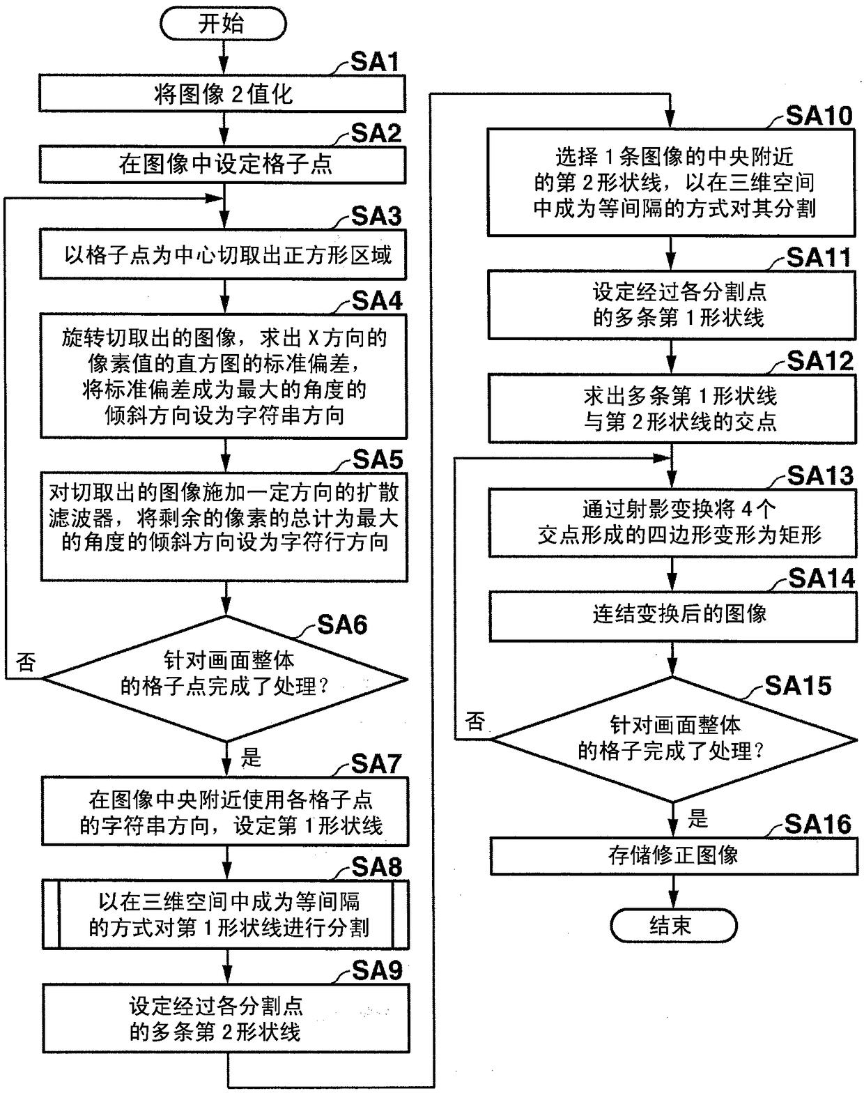
[0129] To summarize first, in the image correction processing of this embodiment, instead of detecting the character line direction from the binarized image G1, a plurality of second shape lines L2 indicating the character line direction are set in the document image.

[0130] Below, according to Figure 11 The image correction processing executed by the control unit 11 in this embodiment will be specifically described with reference to the flowchart shown.

[0131] Also in this embodiment, the control unit 11 first binarizes the document image obtained by imaging the document (step SB1), sets grid points at a plurality of posit...


PUM


Abstract

The present invention provides an image correction device for correcting the distortion of an image obtained by photographing a predetermined object, based on the positional relationship of each point on the predetermined object in the image in two-dimensional space and the photographing angle relative to the surface of the predetermined object. For the positional relationship of each point in three-dimensional space, the deformation information of the image reflecting the determined positional relationship of each point in three-dimensional space is obtained, and the deformation of the image is corrected based on the obtained deformation information. The determination unit is based on the relationship between the shape line in the column direction and the shape line in the row direction set in consideration of the characteristics of the character string on the plane of the plane part of the predetermined object in the image, and the movement direction of each point on the three-dimensional space. Assuming that a plurality of micro-intervals is determined, the acquisition unit acquires deformation information of the plurality of micro-intervals determined by the determination unit, and the correction unit deforms the plurality of micro-intervals according to the deformation information acquired by the acquisition unit to correct the distortion of the image.

Description

technical field [0001] The present invention relates to a technique for correcting distortion of a predetermined object in an image obtained by photographing the predetermined object. Background technique [0002] When the information (characters, graphics, etc.) recorded on the surface of a deformable subject (prescribed object) such as a paper medium (such as a notebook or a book) is photographed and stored as an image, it is possible to implement the Keystone correction to obtain an image that reflects the original shape of the subject. [0003] In addition, in this specification, such a subject may be referred to as a "manuscript", and the term "manuscript" at this time does not refer to a draft or draft, but refers to the paper medium itself that becomes the subject of photography. [0004] However, when an original is photographed, if there is a three-dimensional deformation (overall curvature, irregular local curvature) in the original, if only trapezoidal deformatio...

Claims


Application Information

Patent Timeline
Patent Type & Authority Patents(China)
IPC IPC(8): H04N1/387
CPCG06T5/006G06T2207/30176
Inventor 前野泰士
Owner CASIO COMPUTER CO LTD
Learn More