Eureka AIR delivers breakthrough ideas for toughest innovation challenges, trusted by R&D personnel around the world.

Electric wire erecting device

A wire and frame technology, applied in the field of wire erection devices, can solve problems such as economic loss and traffic impact, and achieve the effect of reducing economic loss

Inactive Publication Date: 2015-06-24
STATE GRID CORP OF CHINA +1
View PDF6 Cites 2 Cited by
  • Summary
  • Abstract
  • Description
  • Claims
  • Application Information

AI Technical Summary

Problems solved by technology

[0003] The purpose of the present invention is to provide a wire erection device to solve the technical problems existing in the prior art that affect traffic and cause economic losses

Method used


Image

  • Electric wire erecting device
  • Electric wire erecting device
  • Electric wire erecting device

Examples


Embodiment Construction

[0024] The technical solutions of the present invention will be clearly and completely described below in conjunction with the accompanying drawings. Apparently, the described embodiments are some of the embodiments of the present invention, but not all of them. Based on the embodiments of the present invention, all other embodiments obtained by persons of ordinary skill in the art without making creative efforts belong to the protection scope of the present invention.

[0025] In the description of the present invention, it should be noted that the terms "center", "upper", "lower", "left", "right", "vertical", "horizontal", "inner", "outer" etc. The indicated orientation or positional relationship is based on the orientation or positional relationship shown in the drawings, and is only for the convenience of describing the present invention and simplifying the description, rather than indicating or implying that the referred device or element must have a specific orientation, ...


PUM


Abstract

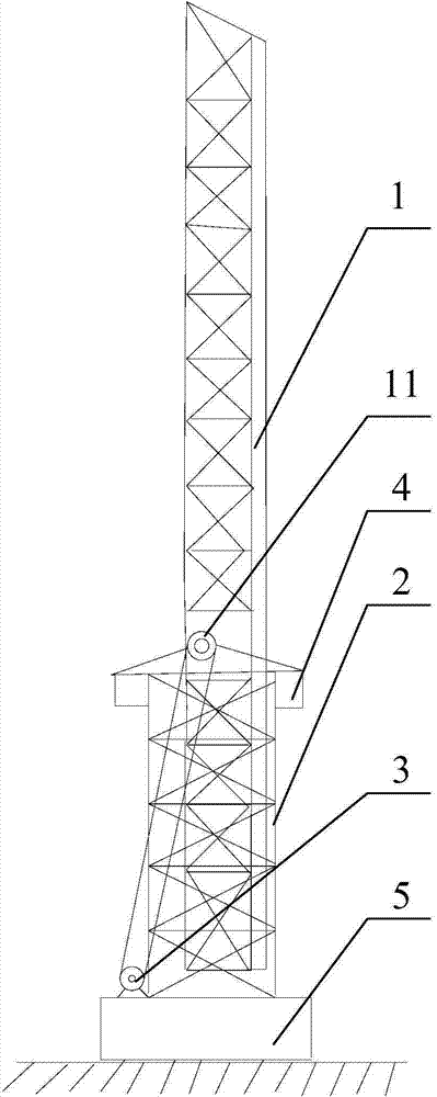
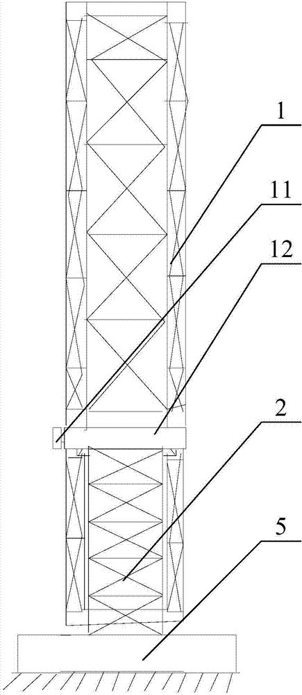
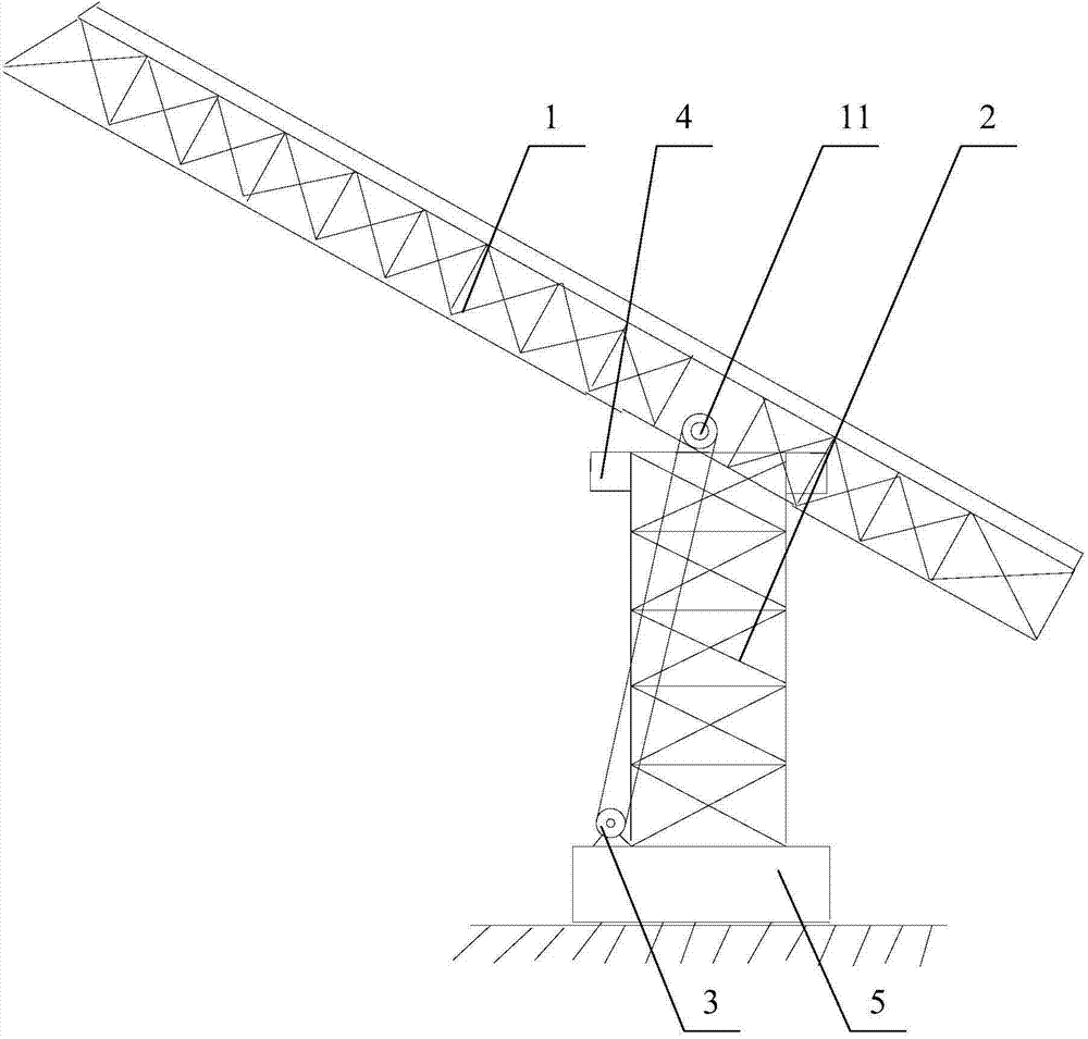
The invention relates to the field of electric wire laying technologies, in particular to an electric wire erecting device which comprises a vertical support, a transverse arm and a driving mechanism. The transverse arm is rotationally connected to the upper end of the vertical support, and the lower end of the vertical support is used for being fixed onto the surface of the ground; the driving mechanism is in transmission connection with the transverse arm and is used for driving the transverse arm to rotate relative to the vertical support. The electric wire erecting device has the advantages that the vertical support can be arranged on a side of a highway or a railway or a river by high-altitude wire erecting staffs, then the transverse arm can be rotationally connected with the upper end of the vertical support, and the driving mechanism can be in transmission connection with the transverse arm; the driving mechanism can be started, and the transverse arm can rotate relative to the vertical support, is perpendicular to the vertical support and further can cross the highway or the railway; the high-altitude wire erecting staffs can carry out operation on the transverse arm at the moment, electric wires can move along the vertical support and the transverse arm without affecting running of vehicles on the highway below the transverse arm or running of trains on the railway or ships on the river, and accordingly economic loss can be reduced to the great extent.

Description

technical field [0001] The invention relates to the technical field of wire laying, in particular to a wire erecting device. Background technique [0002] With the continuous increase of human electricity consumption, more and more cables are laid, for example: laying cables underground, laying cables under river beds or erecting cables at high altitudes, etc. Among them, when erecting cables at high altitude, they sometimes pass through highways, railways or across rivers. When laying power lines through highways, railways or across rivers, it is usually necessary to restrict the traffic of highways, railways or rivers, thereby affecting traffic and causing economic losses. Contents of the invention [0003] The object of the present invention is to provide an electric wire erecting device to solve the technical problems existing in the prior art that traffic is affected and economic losses are caused. [0004] An electric wire erection device provided by the present in...

Claims


Application Information

Patent Timeline
Patent Type & Authority Applications(China)
IPC IPC(8): H02G1/02
Inventor 陈跃中饶金华朱小军黄鲁洪
Owner STATE GRID CORP OF CHINA
Why Eureka
Eureka Blog
Learn More