
Magnetic sealing device for reaction chamber

A reaction chamber and sealing device technology, applied in transportation and packaging, conveyor objects, electrical components, etc., can solve the problems of rubber seals susceptible to corrosion, seal failure, deformation, etc., and achieve easy implementation, stable movement, and positioning. controllable effect

Active Publication Date: 2015-06-24
BEIJING SEVENSTAR ELECTRONICS CO LTD
View PDF3 Cites 1 Cited by
  • Summary
  • Abstract
  • Description
  • Claims
  • Application Information

AI Technical Summary

Problems solved by technology

However, the disadvantage of simply using rubber seals as the sealing medium is that the rubber seals are easily corroded or deformed by high-temperature radiation, resulting in seal failure, and when the reaction chamber door is not evenly pressed against the reaction chamber door hole , is also prone to leakage

Method used


Image

  • Magnetic sealing device for reaction chamber
  • Magnetic sealing device for reaction chamber
  • Magnetic sealing device for reaction chamber

Examples


Embodiment Construction

[0028] The specific embodiment of the present invention will be further described in detail below in conjunction with the accompanying drawings.

[0029] It should be noted that, in the following specific embodiments, when describing the embodiments of the present invention in detail, in order to clearly show the structure of the present invention for the convenience of description, the structures in the drawings are not drawn according to the general scale, and are drawn Partial magnification, deformation and simplification are included, therefore, it should be avoided to be interpreted as a limitation of the present invention.

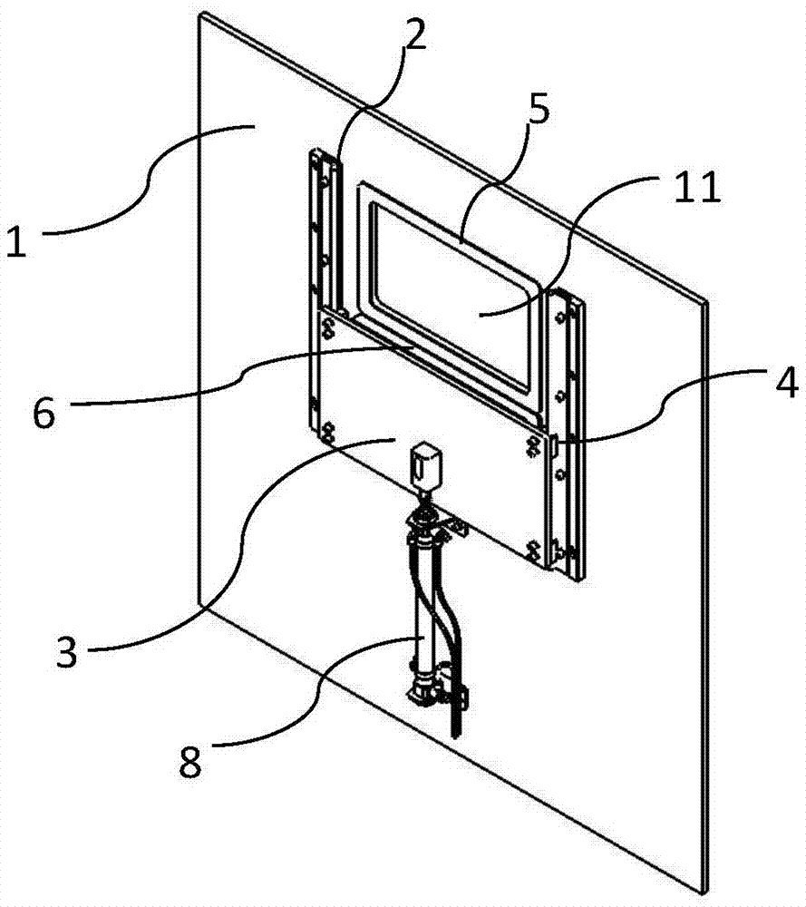
[0030] In the following specific embodiments of the present invention, please refer to figure 1 , figure 1 It is a structural schematic diagram of a magnetic sealing device for a reaction chamber in a preferred embodiment of the present invention. Such as figure 1 As shown, the magnetic sealing device of the reaction chamber of the present inventi...


PUM


Abstract

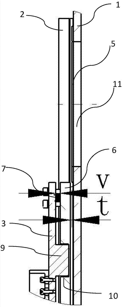
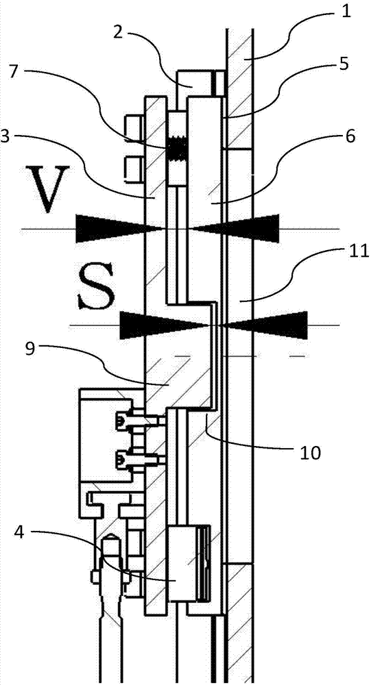
The invention discloses a magnetic sealing device for a reaction chamber. A first magnet and a second magnet which are matched are arranged between corresponding positions of a reaction chamber door hole and a reaction chamber door, the second magnet is connected with the reaction chamber door through a spring, the reaction chamber door hole can be sealed and opened through the heteropolarity attraction principle of the magnets and the tension of the spring, and after a mechanical hand retracts from the reaction chamber, the reaction chamber can be reliably sealed in time. The magnetic sealing device has the remarkable advantages of being simple in structure, easy to obtain and capable of being widely applied to sealing semiconductor washing equipment, an oxidizing furnace and other equipment.

Description

technical field [0001] The invention relates to the field of semiconductor equipment, and more particularly, to a magnetic sealing device for a reaction chamber. Background technique [0002] During the production and processing process of semiconductor integrated circuits, semiconductor wafers (including optical discs or flat panel displays, etc.) usually go through multiple process steps such as film deposition, diffusion, heat treatment, etching, polishing, and cleaning. Many processes are carried out in the reaction chamber, and the wafer is transferred into the reaction chamber by a robot. In order to isolate the reaction chamber from the external environment, prevent the process conditions of the reaction chamber from being disturbed, and avoid adverse reactions and contamination of the wafer, it is necessary to establish a good seal for the reaction chamber. [0003] For example, regarding the cleaning process of wafers, with the development of semiconductor process ...

Claims


Application Information

Patent Timeline
Patent Type & Authority Applications(China)
IPC IPC(8): H01L21/67H01L21/68H01L21/677H01L21/687
Inventor 李广义赵宏宇裴立坤
Owner BEIJING SEVENSTAR ELECTRONICS CO LTD
Learn More