Multi-view Stereo Aerial Camera Device for Unmanned Aerial Vehicle and Method for Determining its Focus Length

A drone and multi-view technology, applied in the field of aerial photogrammetry, can solve the problems of complex structure, structural weight, large volume, large volume and weight, etc., to meet the requirements of small load, simple structure, small volume and weight Effect

Active Publication Date: 2017-11-17
CHINA TOPRS TECH
View PDF1 Cites 0 Cited by
  • Summary
  • Abstract
  • Description
  • Claims
  • Application Information

AI Technical Summary

Problems solved by technology

At present, the most commonly used five-view stereo photogrammetry structure for general aviation, but this type of structure is relatively large in weight and volume, and cannot take into account the characteristics of small loads of light and small UAVs, so it is difficult to use on light and small UAV remote sensing systems
Patent No. CN201310019024.7 discloses an economical airborne tilting digital aerial photography system, including four tilting photography units of front, rear, left and right and a vertical photography unit, suitable for low-altitude remote sensing of UAVs, However, there is no research on the more precise relative spatial position relationship and focal length relationship between the vertical camera and the tilting camera in the light and small UAV aerial photography device in this document, and the photography system in this document uses multiple mechanical fixing parts such as buckle , clamps, etc. to fix the camera, the structure is complex, the volume and weight are large, and it still cannot meet the requirements of light and small UAVs with small loads

Method used


Image

  • Multi-view Stereo Aerial Camera Device for Unmanned Aerial Vehicle and Method for Determining its Focus Length
  • Multi-view Stereo Aerial Camera Device for Unmanned Aerial Vehicle and Method for Determining its Focus Length
  • Multi-view Stereo Aerial Camera Device for Unmanned Aerial Vehicle and Method for Determining its Focus Length

Examples


Embodiment Construction

[0033] The following will clearly and completely describe the technical solutions in the embodiments of the present invention with reference to the accompanying drawings in the embodiments of the present invention. Obviously, the described embodiments are only some, not all, embodiments of the present invention. The components of the embodiments of the invention generally described and illustrated in the figures herein may be arranged and designed in a variety of different configurations. Accordingly, the following detailed description of the embodiments of the invention provided in the accompanying drawings is not intended to limit the scope of the claimed invention, but merely represents selected embodiments of the invention. Based on the embodiments of the present invention, all other embodiments obtained by those skilled in the art without making creative efforts belong to the protection scope of the present invention.

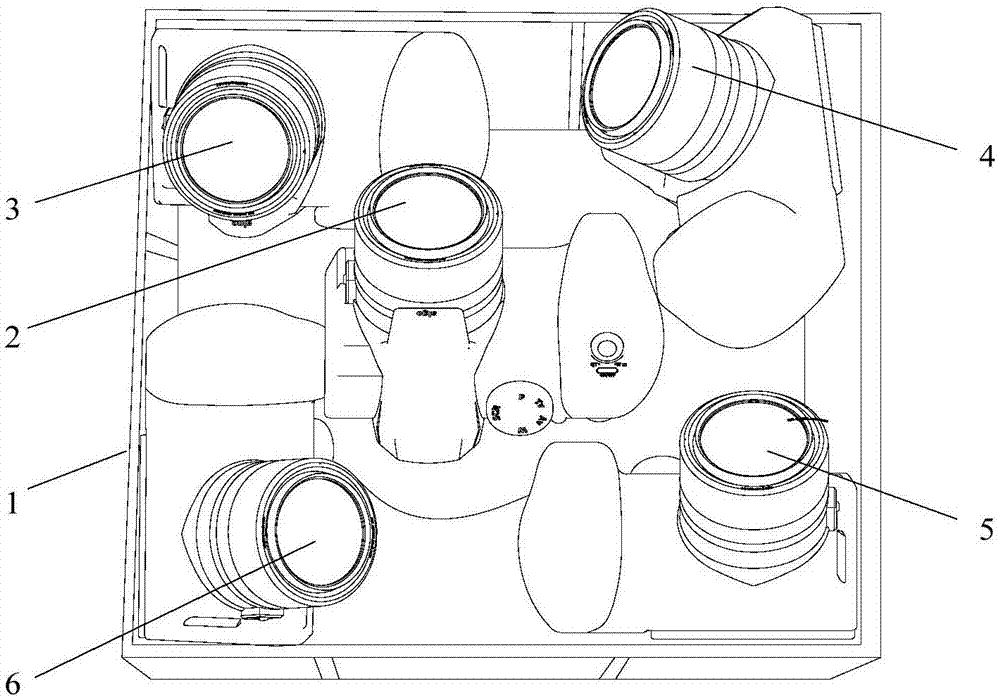
[0034] like figure 1 Shown is a multi-view stereosc...


PUM


Abstract

The invention relates to the field of aerial photogrammetry, in particular to a multi-view stereo aerial photographic device for unmanned aerial vehicles. The multi-view stereo aerial photographic device comprises a connection support, a vertical camera and oblique cameras; an inclination angle alpha y formed by a principle optic axis of the vertical camera and a principle optic axis of each oblique camera is in a range of 40-50 degrees; a focal length f1 of the vertical camera and a focal length f2 of each oblique camera is in a relationship represented by an equation that f2=f1 / cos alpha y. By precise definition of a relative spatial position relationship and the focal length relationship between the principle optic axis of the vertical camera and the principle optic axis of each oblique camera, texture information of the top and lateral sides of a building can be acquired at the same time. Moreover, the multi-view stereo aerial photographic device is simple in structure, small in size and weight and capable of well meeting the requirement of light-small unmanned aerial vehicles on low load.

Description

technical field [0001] The invention relates to the field of aerial photogrammetry, in particular to a multi-view stereo aerial photography device for unmanned aerial vehicles and a method for determining its focal length. Background technique [0002] In recent years, oblique photography technology, as a comprehensive high-tech, has gradually opened a new chapter in the development of international surveying, mapping and remote sensing. It collects images from different angles such as vertical and tilt by carrying multiple sensors with different camera angles on the same flight platform to obtain more complete and accurate information on ground objects. Airborne oblique photography subverts the vertical photography mode of traditional aerial photography. The multi-angle oblique images it collects conform to the real and intuitive world of human vision, and the spatial information is more abundant, complete and friendly, and has a wide range of application prospects. As an ...

Claims


Application Information

Patent Timeline
Patent Type & Authority Patents(China)
IPC IPC(8): G01C11/02G01M11/00
CPCG01C11/00
Inventor 李英成刘飞丁晓波杨江江任亚锋刘沛
Owner CHINA TOPRS TECH
Why Eureka
Try Eureka