Cooking appliance

A technology for cooking utensils and blocking blocks, which is applied to the covers of cooking utensils, cooking utensils, household utensils, etc., can solve problems such as inconvenience in use

Active Publication Date: 2015-06-24
GREE ELECTRIC APPLIANCES INC
View PDF6 Cites 4 Cited by
  • Summary
  • Abstract
  • Description
  • Claims
  • Application Information

AI Technical Summary

Problems solved by technology

Although this solution can realize remote exhaust, the exhaust button must be held down by hand during the exhaust process. When the hand is released, the pressure limiting valve will restore the seal, which is very inconvenient to use.

Method used


Image

  • Cooking appliance
  • Cooking appliance
  • Cooking appliance

Examples


Embodiment Construction

[0026] It should be noted that, in the case of no conflict, the embodiments in the present application and the features in the embodiments can be combined with each other. The present invention will be described in detail below with reference to the accompanying drawings and examples.

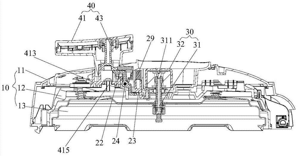
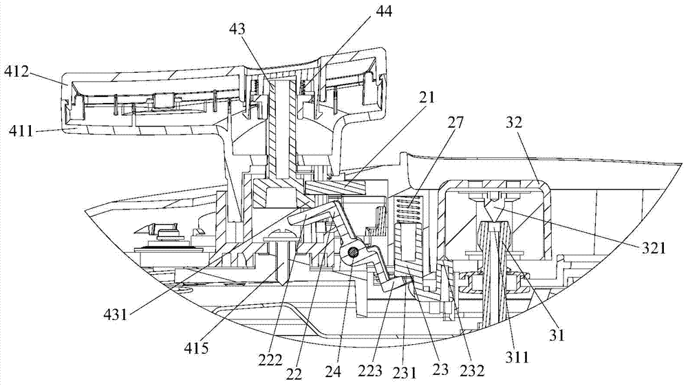
[0027] Such as Figure 1 to Figure 4 As shown, the present invention provides a cooking appliance, which includes a pot body (not shown in the figure), a pot cover 10 , a pressure limiting exhaust device 30 , a driving part 40 and a transmission part 20 .

[0028] Specifically, the pressure limiting exhaust device 30 communicates with the inner cavity of the pot body, and the driving part 40 is connected with the pot cover 10 . Wherein, the transmission part 20 includes a block 21 and a linkage plate 22 . The block 21 is rotatably arranged on the pot cover 10 , and the linkage plate 22 is rotatably arranged on the pot cover 10 and is located below the block 21 . The driving part 40 has a fir...


PUM


Abstract

The invention provides a cooking appliance. The cooking appliance comprises a pot body, a pot lid arranged on the pot body, a pressure-limiting evacuation device, a drive portion and a transmission portion, wherein the pressure-limiting evacuation device is communicated with a cavity of the pot body, and the drive portion is connected with the pot lid. The transmission portion comprises a clamping block and a linkage plate, wherein the clamping block is rotatably arranged on the pot lid, and the linkage plate is rotatably arranged on the pot lid and is positioned below the clamping block. The drive portion is provided with a first drive position clamped between the clamping block and the linkage plate to open the pressure-limiting evacuation device, so that the cooking appliance is in the evacuation state; the drive portion also is provided with a second drive position abutted to one side of the clamping block to close the pressure-limiting evacuation device, so that the cooking appliance is in the sealed state. The drive portion can be clamped between the clamping block and the linkage plate, in other words, the drive portion is locked, and accordingly, evacuation can be achieved without pressing the drive portion with a hand, and possibility of scalding caused by evacuation can be reduced. The cooking appliance is simple in structure, safe and reliable.

Description

technical field [0001] The present invention relates to household appliances, in particular to a cooking utensil. Background technique [0002] After the cooking work of the existing electric pressure cooker is completed, because the pressure inside the pot is relatively high, before opening the pot cover, the operator sometimes needs to lift the pressure limiting valve by hand or rotate it to exhaust air. The temperature of the steam ejected during the exhaust is very high, and the operating handle is on the pressure limiting valve body, so there is a risk of hand burns during the operation. [0003] There is an electric pressure cooker exhaust structure in the prior art, that is, the exhaust operating device is composed of an exhaust button installed on the handle of the pot cover, a lever transmission rod installed on the handle seat and a sliding top block, and the lower end of the exhaust button is connected with the transmission rod. One end of the drive rod is connec...

Claims


Application Information

Patent Timeline
Patent Type & Authority Applications(China)
IPC IPC(8): A47J36/06A47J27/08A47J36/38
Inventor 赖达英韦坤生柏长升麦焕
Owner GREE ELECTRIC APPLIANCES INC
Why Eureka
Try Eureka