Zero-current-ripple full-bridge grid-connected inverter circuit
A full-bridge inverter circuit, inverter circuit technology, applied in the direction of converting AC power input to DC power output, electrical components, output power conversion devices, etc. problems, to achieve the effect of reducing requirements and improving the quality of output current
- Summary
- Abstract
- Description
- Claims
- Application Information
AI Technical Summary
Problems solved by technology
Method used
Image
Examples
Embodiment 1
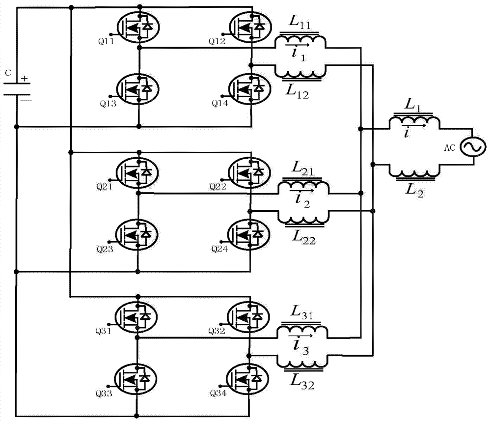
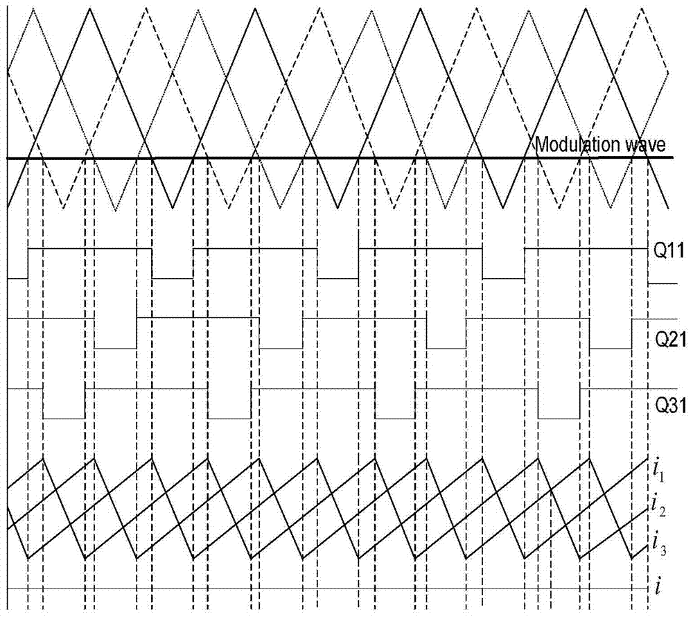
[0013] No current ripple full bridge grid-connected inverter circuit diagram figure 1 In order to connect, the black dots on the two intersecting lines indicate that the two lines are connected to each other, and no black dots indicate that there is no connection between the two lines. figure 1 The three sets of full-bridge grid-connected inverter circuits in the series are connected in parallel, and then connected to the single-phase grid after two filter inductors are connected in series. Each set of full-bridge inverter circuits is composed of four switch tubes and two high-frequency filter inductors. The parallel-connected full-bridge grid-connected inverter circuits respectively output grid-connected currents with equal amplitudes. figure 2 The three sets of parallel full-bridge inverter circuits all adopt unipolar modulation, and the phases of the three sets of high-frequency modulation signal triangular waves are 120° apart, while ensuring that the inductor current in ...
PUM
 Abstract
Description
Claims
Application Information
 - R&D
- Intellectual Property
- Life Sciences
- Materials
- Tech Scout
- Unparalleled Data Quality
- Higher Quality Content
- 60% Fewer Hallucinations
Browse by: Latest US Patents, China's latest patents, Technical Efficacy Thesaurus, Application Domain, Technology Topic, Popular Technical Reports.
© 2025 PatSnap. All rights reserved.Legal|Privacy policy|Modern Slavery Act Transparency Statement|Sitemap|About US| Contact US: help@patsnap.com


