Automatic correction system and automatic correction method

A technology of automatic correction and movement, which is applied in the direction of instruments, electrical digital data processing, and input/output process of data processing, etc. It can solve problems such as personnel flow, large size variation, and manual test quality cannot be stabilized.

Active Publication Date: 2015-06-17
IND TECH RES INST
View PDF3 Cites 5 Cited by
  • Summary
  • Abstract
  • Description
  • Claims
  • Application Information

AI Technical Summary

Problems solved by technology

[0003] At present, the product function (especially the touch function) test of the tablet before shipment is mostly carried out manually. However, due to the difficulty of consistent training of personnel and the problem of personnel turnover, the quality of manual testing often cannot be stabilized. , and the person responsible for the detection must have considerable proficiency and stability, otherwise there will be vibration or stagnation when touching, which will cause abnormal test results. Therefore, the visual imaging system is introduced and combined with the automatic detection method of the mobile platform has become a trend
[0004] However, since the touch display panel faces many product specifications and styles, and the size varies greatly, it is necessary to adjust the field of view of the visual imaging system frequently during testing. If the visual field of the visual imaging system is adjusted (for example, the field of view changes), It is necessary to re-calibrate the visual imaging system to correctly move the position of the touch test according to the identification results of the visual imaging system. Re-calibration of the visual imaging system will take many steps and time, so there is still room for improvement

Method used


Image

  • Automatic correction system and automatic correction method
  • Automatic correction system and automatic correction method
  • Automatic correction system and automatic correction method

Examples


Embodiment Construction

[0027] The implementation manners of the present disclosure are described below through specific specific examples, and those skilled in the art can easily understand other advantages and effects of the present disclosure from the content disclosed in this specification.

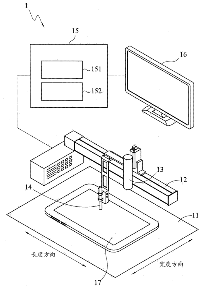
[0028] It should be noted that the structures, proportions, sizes, etc. shown in the drawings of this specification are only used to match the content disclosed in the specification for the understanding and reading of those skilled in the art, and are not used to limit the conditions that this disclosure can implement , so it has no technical substantive significance. Any modification of the structure, change of the proportional relationship or adjustment of the size shall still fall under the The technical content must be within the scope covered. At the same time, terms such as "one", "upper", "L-shaped", "T-shaped", "end point", "corner", "long", "wide" and "middle" cited in this specification , is only...


PUM


Abstract

An automatic correction system and an automatic correction method are disclosed. The system comprises a bearing platform, a mobile module, an image pick-up unit, a display unit, a touch unit and a processing module. The bearing platform is provided with a touch display panel thereon. The touch display panel displays a mark at a portion which is pressed. The mobile module is arranged on the bearing platform and can move relative to the bearing platform. The image pick-up unit is arranged on the mobile module. The display unit is connected with the image pick-up unit and used for displaying images obtained by the image pick-up unit. The touch unit is arranged on the mobile module. The processing module is connected with the mobile module and the image pick-up unit and comprises an image identification unit and a mobile module control unit. The invention can automatically and rapidly complete correction of a visual image pick-up system.

Description

technical field [0001] The disclosure relates to a calibration system and a calibration method, in particular to an automatic calibration system and an automatic calibration method. Background technique [0002] With the vigorous development of tablet PCs, the total global shipments of tablet PCs are expected to exceed the total global shipments of notebook computers in a few years, and tablet PCs will become a common electronic product in human life in the future. [0003] At present, the product function (especially the touch function) test of the tablet before shipment is mostly carried out manually. However, due to the difficulty of consistent training of personnel and the problem of personnel turnover, the quality of manual testing often cannot be stabilized. , and the person responsible for the detection must have considerable proficiency and stability, otherwise there will be vibration or stagnation when touching, which will cause abnormal test results. Therefore, the...

Claims


Application Information

Patent Timeline
IPC IPC(8): G06F3/041
Inventor 蔡雅惠黄国唐刘俊贤
Owner IND TECH RES INST
Why Eureka
Try Eureka