
Paper cutting device

A cutting device and paper technology, applied in metal processing and other directions, can solve the problems of blade service life impact, low adaptability, difficult adjustment, etc., and achieve the effect of reducing operation difficulty, improving production efficiency, and reliable cutting

Inactive Publication Date: 2015-06-17
郭超毅
View PDF8 Cites 5 Cited by
  • Summary
  • Abstract
  • Description
  • Claims
  • Application Information

AI Technical Summary

Problems solved by technology

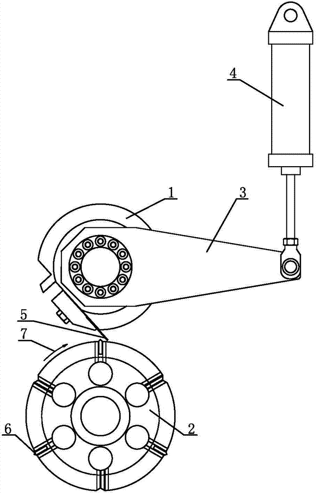
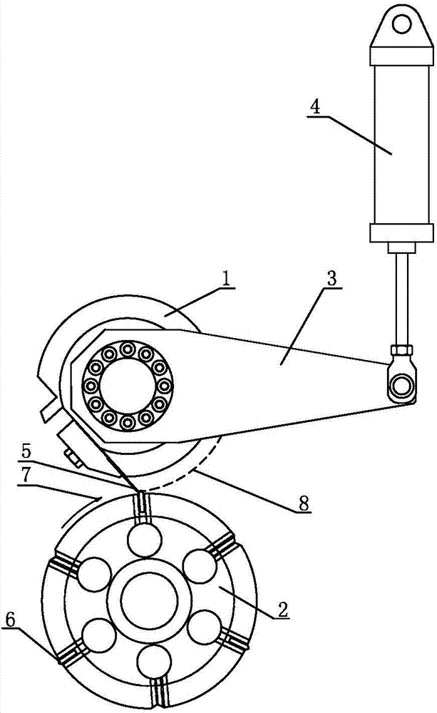
Limited by the diameter of the circumference of the vacuum folding roller 2 itself, the cutting termination point of the upper cutting knife 5 and the lower cutting knife 6 should not be too far from the highest point of rotation of the lower cutting knife 6, otherwise the upper cutting knife 5 and the lower knife 6 cannot Cutting in the normal state cannot guarantee the cutting effect, but the large-width paper folding machine requires that the cutting angle between the upper knife 5 and the lower knife 6 should not be too small, otherwise the upper knife 5 and the lower knife 6 will not be too small. If the shearing force is too large, the cutting effect cannot be guaranteed, the adjustment of the cutting tool will become very difficult, and the service life of the blade will be seriously affected
Therefore, the paper cutting device used for folding machines in the prior art has disadvantages such as low adaptability and difficult adjustment.

Method used


Image

  • Paper cutting device
  • Paper cutting device
  • Paper cutting device

Examples


Embodiment Construction

[0023] The present invention will be described in further detail below in conjunction with the accompanying drawings.

[0024] Figure 4~6 A paper cutting device according to an embodiment of the present invention is schematically shown. Such as Figure 4 with Image 6 As shown, the device includes a frame 10 , a cutting upper knife roller 1 , a vacuum folding roller 2 , a swing arm 30 and a driving device 40 , the vacuum folding roller 2 is supported by the frame 10 , and the driving device 40 is installed on the frame 10 . Both the swing arm 30 and the driving device 40 are two, and are separately arranged at the two ends of the cutting upper knife roller 1 . The cutting upper knife roller 1 axis is equipped with a cutting upper knife 5, and the vacuum folding roller 2 is axially equipped with a cutting lower knife 6. Wherein, the arrow 7 is the rotation direction of the vacuum folding roller 2 .

[0025] One end of the swing arm 30 is connected with the end of the cutt...


PUM


Abstract

The invention discloses a paper cutting device. The paper cutting device comprises a frame, a cutting upper knife roller, a vacuum folding roller, a swinging arm and a driving device, wherein the vacuum folding roller is supported by the frame; projections of central axis of the cutting upper knife roller and the vacuum folding roller on the horizontal plane have an intersecting point; the driving device is mounted on the frame; one end of the swinging arm is connected with the end part of the cutting upper knife roller, and the other end is mounted on the frame; and one end, connected with the cutting upper knife roller, of the swinging arm is in fit connection with the driving device. The process of avoiding a cutting upper knife is to vertically move the cutting upper knife roller, so that the paper cutting device can prevent the interference with the vacuum folding roller, and the cutting upper knife and a cutting lower knife can cut by a larger cutting included angle so as to realize reliable cutting of large-breadth papers. Therefore, the device cutting device is suitable for cutting papers with various breadths; and the adjustment of the cutting knives is not limited by the swinging of the cutting upper knife roller, so that the operation difficulty is reduced, and the production efficiency is improved.

Description

technical field [0001] The invention relates to the technical field of paper folding machines, in particular to a paper cutting device for a folding machine. Background technique [0002] The existing paper folding machine needs to cut the paper according to a certain length and then fold it, such as figure 1 As shown, the paper cutting device is mainly composed of a cutting upper knife roller 1, a vacuum folding roller 2, a swing arm 3, a swing arm driving cylinder 4, a cutting upper knife 5 installed along the axis on the cutting upper knife roller 1, and a vacuum folding roller. 2. The upper and lower cutters 6 are installed along the axial direction, such as figure 2 As shown, cut off the central axis a of the upper knife roller 1 1 a 2 and the central axis b of the vacuum folding roll 2 1 b 2 The projections on the horizontal plane are crossed at an angle. When the paper folding machine is cutting and folding, the cutting upper knife roller 1 is fixed, and the va...

Claims


Application Information

Patent Timeline
Patent Type & Authority Applications(China)
IPC IPC(8): B26D1/40B26D5/12
Inventor 郭超毅
Owner 郭超毅
Learn More