Backlight module

A technology of backlight module and optical film, applied in electric light source, light source fixing, lighting device, etc., can solve problems such as damage and image optical taste

Inactive Publication Date: 2015-06-10
AU OPTRONICS CORP
View PDF3 Cites 7 Cited by
  • Summary
  • Abstract
  • Description
  • Claims
  • Application Information

AI Technical Summary

Problems solved by technology

When the relative displacement between the optical film 30 and the plastic frame 10 occurs, the optical quality may be affected, and even local damage may occur

Method used


Image

  • Backlight module
  • Backlight module
  • Backlight module

Examples


Embodiment Construction

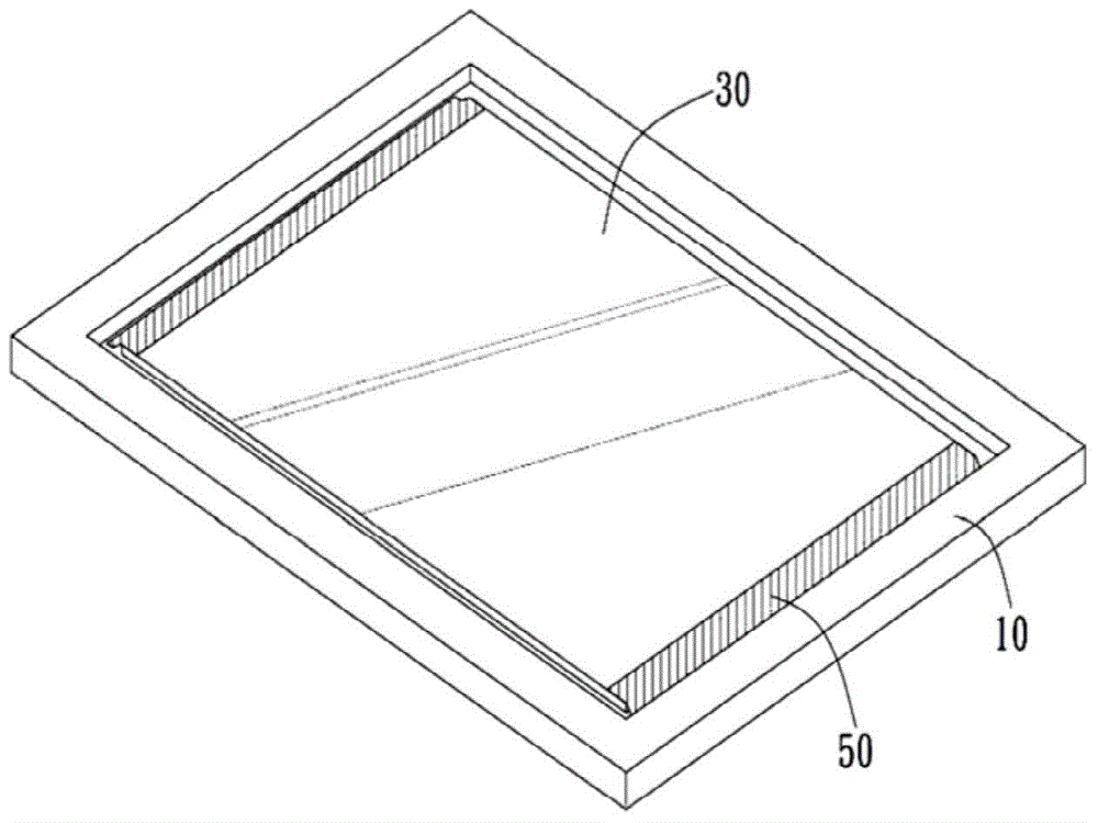
[0037] The invention provides a backlight module. In a specific embodiment, the backlight module is used in conjunction with a liquid crystal display panel or other display panels that require backlight to generate images; however, in different embodiments, the backlight module can also be used in other devices that need to provide backlight.

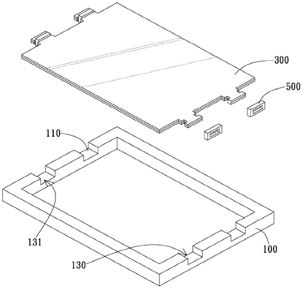
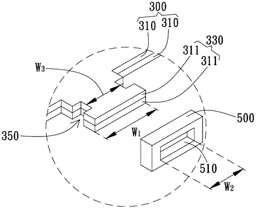
[0038] Please refer to Figure 2A , Figure 2B and image 3 , Figure 2A It is a schematic diagram of explosion of a backlight module according to a specific embodiment of the present invention; Figure 2B for Figure 2A Partial enlarged schematic diagram of ; image 3 It is a schematic side view of a backlight module according to a specific embodiment of the present invention. The backlight module includes a frame 100 , an optical film set 300 and a fixing ring 500 . The frame 100 can be made of plastic, but not limited thereto. In addition, the frame 100 may be formed as a rectangular closed frame, but not limited thereto. In ...


PUM


Abstract

The invention provides a backlight module comprising a frame, an optical film group and a fixed ring; the optical film group is arranged in the frame, so the optical film group is surrounded by the frame or matched with the frame; the optical film group comprises lug directly or indirectly supported by a support face of the frame; the support face supports the lug, so the frame can support the optical film group; two sides of the lug are respectively provided with at least one groove; the fixed ring hoops the lug, and at least part of the fixed ring is clamped in the groove.

Description

【Technical field】 [0001] The present invention relates to a backlight module for a display device; specifically, the present invention relates to a backlight module with an optical film positioning mechanism for a display device. 【Background technique】 [0002] figure 1 Shown is a traditional backlight module structure, including a plastic frame 10 and an optical film 30 . The main function of the optical film 30 is to adjust the optical behavior of light generated by the light source below, and the plastic frame 10 is used to carry the optical film 30 or support the upper display panel. The side of the plastic frame 10 is usually provided with a retaining wall, and the optical film 30 is disposed in the retaining wall and supported by the plastic frame 10 . In order to fix the relationship between the optical film 30 and the plastic frame 10, usually an adhesive tape 50 is attached to the side of the optical film 30 and the plastic frame 10, or between the optical film 30...

Claims


Application Information

Patent Timeline
Patent Type & Authority Applications(China)
IPC IPC(8): F21S8/00F21V17/10
CPCF21S8/00F21V17/10
Inventor 黎平
Owner AU OPTRONICS CORP
Why Eureka
Try Eureka