Welding method of pre-embedded steel bar welded joints at the two ends of primary buckle arch

Active Publication Date: 2017-02-01
CHINA RAILWAY CONSTR BRIDGE ENG BUREAU GRP
View PDF6 Cites 0 Cited by
  • Summary
  • Abstract
  • Description
  • Claims
  • Application Information

AI Technical Summary

Problems solved by technology

This method requires a large amount of steel for construction, and when the position of the steel plate is unreasonable after the position is fixed firmly, it is difficult to adjust the position of the steel plate, resulting in insufficient welding length between the steel bar and the steel plate, and the welding quality cannot meet the design requirements
If reinforcement measures are taken for the joints, the joint connection process will be cumbersome, which will increase the difficulty of construction and reduce the construction speed

Method used


Image

  • Welding method of pre-embedded steel bar welded joints at the two ends of primary buckle arch
  • Welding method of pre-embedded steel bar welded joints at the two ends of primary buckle arch
  • Welding method of pre-embedded steel bar welded joints at the two ends of primary buckle arch

Examples


Embodiment Construction

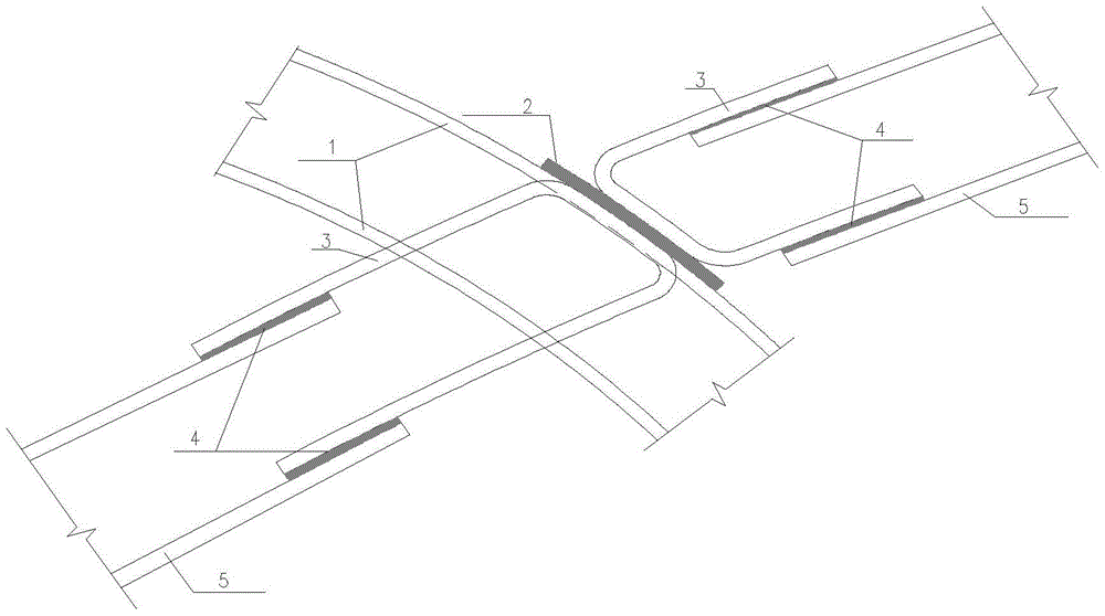
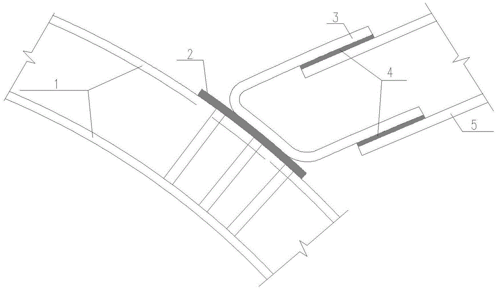
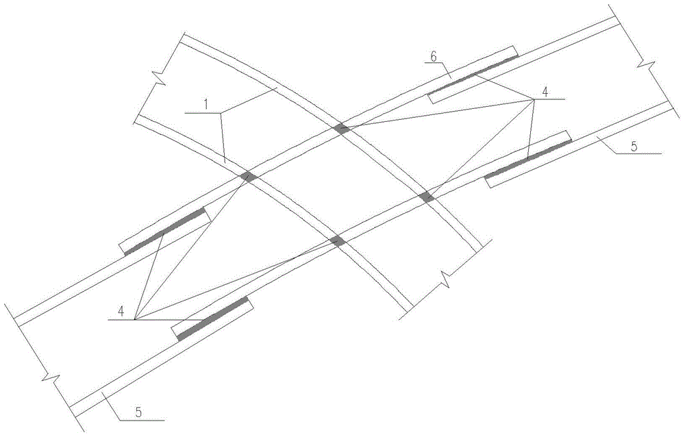
[0016] Such as image 3 , 4 Shown: a welding method for pre-embedded steel bar welding joints at the two ends of the primary buckle arch. When installing the side pilot hole grid, first determine the position and direction of the pre-embedded steel bar, and drill along the pre-embedded direction of the steel bar on the outer soil layer. Set up four soil holes, then insert the pre-embedded steel bar, adjust the direction of the steel bar, press image 3 Weld the intersection of the pre-embedded steel bar and the main bar of the pilot tunnel grid firmly, and ensure that the exposed length of the steel bar exceeds 10 times the diameter of the main bar; Four soil holes are drilled in the outer soil layer along the pre-embedded direction of the steel bar, according to Figure 4 Weld the U-shaped steel bar to the main bar of the pilot hole grid firmly, and ensure that the length of the exposed steel bar exceeds 10 times the diameter of the main bar.

[0017] The present invention...


PUM


Abstract

The invention discloses a method for welding embedded steel bar welding joints of two end nodes in an initial supporting arch. The method comprises the following steps: when a side pilot tunnel grille is mounted, steel bar embedding position and direction are determined first, four soil holes are punched in an outer side soil layer in the steel bar embedding direction, the embedded steel bars are inserted, the directions of the steel bars are adjusted, and then crossing points of the embedded steel bars and a main steel bar of the pilot tunnel grille are welded firmly; when a middle pilot tunnel grille is mounted, the steel bar embedding position and direction on the pilot tunnel grille are determined, four soil holes are punched in the outer side soil layer in the steel bar embedding direction, a U-shaped steel bar and the main steel bar of the pilot tunnel grille are welded firmly. Through the adoption of the method for directly embedding steel bar welding joints, the construction cost is reduced, the node connecting quality is ensured, and the node construction becomes simple and rapid.

Description

[0001] Technical field: [0002] The invention belongs to a building construction method, in particular to a welding method for pre-embedded steel bar welded joints at both ends of an initial buckle arch. Background technique [0003] At present, in the construction of the initial buckle arch of the PBA construction method of the subway station, the method of pre-embedded steel plate (+ U-shaped rib) is mostly used, that is, the method of using U-shaped rib + pre-embedded steel plate for the side arch, and the method of pre-embedded steel plate for the middle arch, (such as figure 1 , 2 shown). This method requires a large amount of steel for construction, and when the position of the steel plate is unreasonable after the position is fixed, it is difficult to adjust the position of the steel plate, resulting in insufficient welding length between the steel bar and the steel plate, and the welding quality cannot meet the design requirements. If reinforcement measures are take...

Claims


Application Information

Patent Timeline
Patent Type & Authority Patents(China)
IPC IPC(8): E21D11/15
CPCB23K31/02E21D11/155
Inventor 曲建生刘龙宋战平
Owner CHINA RAILWAY CONSTR BRIDGE ENG BUREAU GRP
Why Eureka
Try Eureka