
A steam turbine clapboard drawing steel wire alignment device

A steam turbine and steel wire drawing technology, which is applied in metal processing, metal processing equipment, manufacturing tools, etc., can solve the problems of inaccurate control of steel wire tensile stress, inaccurate vertical and horizontal positioning, and inability to effectively adjust the vertical arc of steel wire, etc. , to achieve the effects of easy on-site acquisition, convenient production, and effective control of the tensile stress

Inactive Publication Date: 2017-01-18
WUHAN UNIV OF SCI & TECH
View PDF9 Cites 0 Cited by
  • Summary
  • Abstract
  • Description
  • Claims
  • Application Information

AI Technical Summary

Problems solved by technology

The commonly used method is to align the steel wire. The alignment of the steel wire needs to be adjusted several times. After each adjustment, the steel wire needs to be removed, and then the installation of the next process is carried out. Although the existing steel wire alignment device is simple, However, the positioning in the vertical and horizontal directions is not accurate, and the steel wire needs to be re-aligned when it is reset, which is very inconvenient
In addition, the existing steel wire alignment device does not accurately control the tensile stress of the steel wire, and the vertical arc of the steel wire cannot be effectively adjusted

Method used


Image

  • A steam turbine clapboard drawing steel wire alignment device

Examples


Embodiment 1

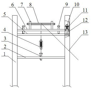
[0019] The utility model relates to a device for aligning steel wires for separating plates of steam turbines. Such as figure 1 As shown, the device includes two channel steels 1, a lower fixed beam 2, an upper fixed beam 5, a movable beam 6, a cylindrical guide rod 12, an adjusting screw 8, an adjusting bolt 9, a fastening bolt 3 and a spring dynamometer 4.

[0020] An upper fixed crossbeam 5 is horizontally fixed on the grooved inner walls of the two channel steels 1 , and cylindrical guide rods 12 are symmetrically fixed on the upper plane near the two ends of the upper fixed crossbeam 5 . Two ends near the movable crossbeam 6 are provided with round holes, and the movable crossbeam 6 is looped over the upper fixed crossbeam 5 through the round hole and the cylindrical guide rod 12 . A spring 11 is installed on the top of the cylindrical guide rod 12, and the spring 11 is located between the movable beam 6 and the nut 10.

[0021] Both sides of the middle position of the ...


PUM


Abstract

The invention relates to an aligning device for a drawn steel wire of a turbine partition plate. According to the technical scheme, cylinder guide rods (12) are symmetrically arranged at the two ends of an upper fixed cross beam (5), a movable cross beam (6) is movably arranged at the position above the upper fixed cross beam (5) through the cylinder guide rods (12) in a sleeving mode, an adjusting threaded rod (8) is horizontally installed above the movable cross beam (6), adjusting bolts (9) are symmetrically arranged on the outer sides of a threaded rod supporting plate (7), the lower ends of the adjusting bolts (9) are in contact with the upper plane of the upper fixed cross beam (5), a fastening bolt (3) is arranged in the middle of a lower fixed cross beam (2), one end of the steel wire (13) penetrates through the turbine partition plate and is fixed to an aligning device, located on the other side, for the drawn steel wire of the turbine partition plate, the other end of the steel wire (13) is wound around the adjusting threaded rod (8) to be connected with the upper end of a spring force meter (4), and the lower end of the spring force meter (4) is connected with the fastening bolt (3). The aligning device is simple in structure and convenient to manufacture. By the adoption of the aligning device, the steel wire (13) can be rapidly and accurately located in the vertical and horizontal directions, and the pulling stress of the steel wire can be effectively controlled.

Description

technical field [0001] The invention belongs to the technical field of alignment of steam turbine clapboards. In particular, it relates to a straightening device for drawing steel wires of a steam turbine clapboard. Background technique [0002] In steam turbine installation, finding the partition is a very important link. Commonly used alignment methods include laser alignment, false shaft alignment and steel wire alignment. Among them, the laser alignment accuracy is the highest, but the laser alignment is greatly affected by the conditions. When the external interference airflow affects the beam, the beam needs to be readjusted to keep the reference unchanged. False shaft alignment is to use the false shaft made of steel pipe to replace the steam turbine rotor for alignment. Although the false shaft alignment has the characteristics of high measurement accuracy, the production and storage requirements of the false shaft are high, so it is also very important in engineer...

Claims


Application Information

Patent Timeline
Patent Type & Authority Patents(China)
IPC IPC(8): B23P19/10
CPCB23P19/107
Inventor 欧阳惠王琦琳庄羽航涂福泉陈奎生曾良才周浩胡升谋吕杰毛阳
Owner WUHAN UNIV OF SCI & TECH
Learn More