One-way valve

A one-way valve and one-way valve technology, applied in the direction of control valve, valve device, functional valve type, etc., can solve the problems of the valve core of the valve port being stuck, increasing the cost, and failing to achieve a sealing effect.

Inactive Publication Date: 2015-06-03
CHANGZHOU XINJIANGNAN ENERGY EQUIP
View PDF0 Cites 4 Cited by
  • Summary
  • Abstract
  • Description
  • Claims
  • Application Information

AI Technical Summary

Problems solved by technology

However, due to the frequent work and closing and opening of the one-way valve, the spool of the valve port will be stuck after a period of use, resulting in backflow of the medium or failure to achieve a good sealing effect.
At this time, the one-way valve needs to be replaced, which increases the cost

Method used


Image

  • One-way valve

Examples


Embodiment Construction

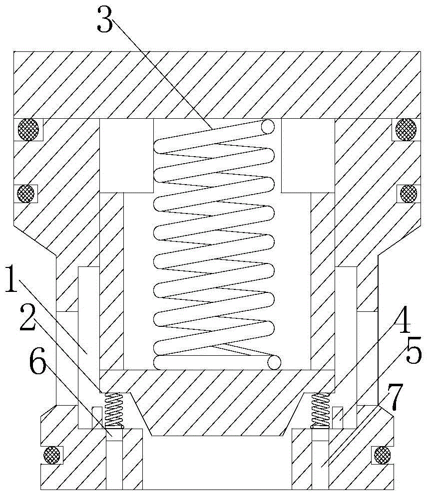
[0014] See figure 1 As shown, the one-way valve includes a valve body 1 and a valve core 2 installed in the valve body. The bottom surface of the valve core is provided with a support spring 3, and the inner wall of the valve body inlet is provided with a first elastic Piece 4; The first elastic piece is provided with a baffle 5 on the inner wall of the valve body on the side opposite to the inlet. Since the elastic part is also designed on the top surface of the spool, the upward pulling force of the spool is increased, and the problem that the check valve is not tightly sealed and the spool is stuck causing the medium to flow back during the locking process is solved.

[0015] A support rod 6 is provided at the connection between the first elastic member and the inner wall surface, and the top end of the support rod is located in the small hole 7 on the inner wall surface of the entrance. The support rod is used to fix the elastic member to prevent the elastic member from bend...


PUM


Abstract

The invention relates to the technical field of valve devices, in particular to a one-way valve. A first elastic part is arranged on the inner wall surface of an inlet of a one-way valve body, and a baffle plate is arranged on the first elastic part and on the inner wall surface of the valve body on one side opposite to the inlet. The one-way valve solves the problem of untight locking in the locking process.

Description

Technical field [0001] The invention relates to the technical field of valve devices, in particular to one-way valves. Background technique [0002] One-way valve is a directional control valve in which air flow can only flow in one direction but not in the reverse direction. Its working principle is the same as the hydraulic one-way valve. Compressed air enters from the inlet, overcoming the spring force and friction force to open the valve port of the one-way valve, and the compressed air flows from the inlet to the valve body; when there is no compressed air at the inlet, under the action of the spring force and the remaining air force of the valve body cavity; The port is in a closed state, so that the air flow from the cavity of the valve body to the inlet is blocked. However, due to the frequent working and closing and opening of the one-way valve, the valve core of the valve port will be stuck after a period of use, causing the medium to flow back or failing to achieve a...

Claims


Application Information

Patent Timeline
Patent Type & Authority Applications(China)
IPC IPC(8): F16K15/02
CPCF16K15/025
Inventor 韩培
Owner CHANGZHOU XINJIANGNAN ENERGY EQUIP
Why Eureka
Try Eureka