
Auxiliary structure and construction method for entering hole of rectangular pipe jacking machine

A technology of rectangular pipe jacking and construction methods, which is applied to earth drilling, mining equipment, tunnels, etc., and can solve problems such as the inability of rectangular pipe jacking machines to enter holes

Active Publication Date: 2017-02-22
SHANGHAI MECHANIZED CONSTR GRP
View PDF5 Cites 0 Cited by
  • Summary
  • Abstract
  • Description
  • Claims
  • Application Information

AI Technical Summary

Problems solved by technology

[0004] The purpose of the present invention is to provide an auxiliary structure and construction method suitable for the entry of a rectangular pipe jacking machine in an existing building, so as to solve the problem that the rectangular pipe jacking machine cannot smoothly enter the hole in an existing building in the prior art. The problem

Method used


Image

  • Auxiliary structure and construction method for entering hole of rectangular pipe jacking machine
  • Auxiliary structure and construction method for entering hole of rectangular pipe jacking machine

Examples


Embodiment 1

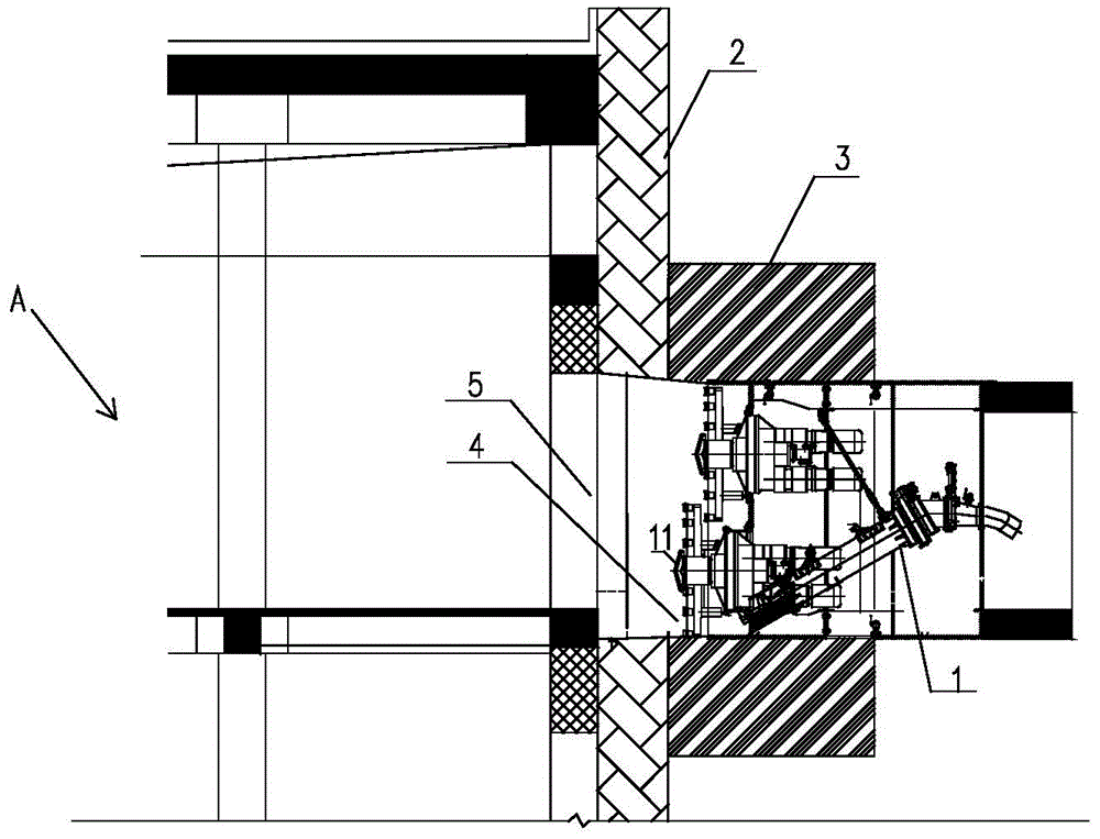
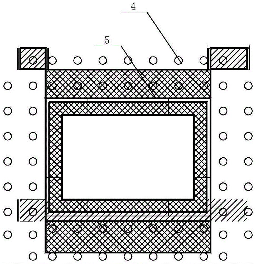
[0030] Combine below figure 1 and figure 2 The auxiliary structure for entering the hole of the rectangular pipe jacking machine of the present invention will be described in detail.

[0031] Such as Figure 1 to Figure 2 As shown, the auxiliary structure of the rectangular pipe jacking machine 1 entering the hole is suitable for the installation of the rectangular pipe jacking machine 1 when the receiving shaft cannot be installed in the existing building A and the cutter head 11 of the rectangular pipe jacking machine 1 is close to the underground diaphragm wall 2 Entering the hole, including the door reinforcement freezing structure 3 and the steel frame structure 4, the door reinforcement freezing structure 3 is arranged longitudinally along the 5th circle of the door; the steel frame structure 4 is an assembled closed steel structure with openings at both ends, and the steel frame structure 4 The openings at both ends of the opening match the shape and size of the door...

Embodiment 2

[0035] Continue to combine below figure 1 and figure 2 The construction method of the rectangular pipe jacking machine 1 entering the hole will be described in detail. The construction method for entering a hole with a rectangular pipe jacking machine 1 includes the following steps:

[0036] Step 1: Park the rectangular pipe jacking machine 1 at a predetermined position, so that the cutter head 11 of the rectangular pipe jacking machine 1 is close to the underground continuous wall 2 .

[0037] Specifically, firstly, check the centers of the starting portal and the receiving portal 5 of the rectangular pipe jacking machine 1 . According to the center positions of the two portals, the actual slope and distance of the rectangular pipe jacking machine 1 are measured and calculated, and the best stop position of the rectangular pipe jacking machine 1 is simulated. When the distance from the underground diaphragm wall 2 of the receiving portal 5 is about 5 meters, the constructio...


PUM


Abstract

The invention discloses a rectangular pipe jacking machine tunnel entering auxiliary structure and construction method and belongs to the technical field of underground space development. The auxiliary structure comprises a tunnel portal reinforcing freezing structure and a steel frame structure, wherein the tunnel portal reinforcing freezing structure is longitudinal disposed along the peripheral ring of a tunnel portal; the steel frame structure is a spliced sealed steel structure with openings in two ends, the openings of the steel frame structure are matched with the tunnel portal in shape and size, one end of the steel frame structure is fixedly connected with one end of the shell of a rectangular pipe jacking machine, and the other end of the steel frame structure is fixedly connected with tunnel portal. The construction method includes: allowing a rectangular pipe jacking machine tool bit to stop when closely attaching to an underground continuous wall; constructing the tunnel portal reinforcing freezing structure; chiseling off reinforced concrete at the tunnel portal, and mounting the steel frame structure which is in seamless butt joint with the tunnel portal and the shell respectively; removing the rectangular pipe jacking machine, reserving the shell, and constructing a cast-in-place concrete structure by using the steel frame structure as an outer form board at the same time; unfreezing the tunnel portal reinforcing freezing structure and performing grouting reinforcement on the tunnel portal area.

Description

technical field [0001] The invention belongs to the technical field of underground space development, and in particular relates to an auxiliary structure and a construction method for a rectangular pipe jacking machine to enter a hole. Background technique [0002] With the development of urbanization, the development of urban underground space is becoming more and more frequent. The rectangular pipe jacking machine can improve the utilization rate of space more than the circular pipe jacking machine. Generally speaking, when the rectangular pipe jacking machine is in operation, it is hoisted in the originating shaft, excavated through the tunnel between the originating shaft and the receiving shaft, and then enters the hole from the receiving shaft, and then hoisted to the ground for receiving. [0003] However, due to the limitation of the existing buildings, after the rectangular pipe jacking machine completes the tunnel excavation, the receiving shaft cannot be set up a...

Claims


Application Information

Patent Timeline
Patent Type & Authority Patents(China)
IPC IPC(8): E21D9/00
CPCE21D9/14
Inventor 张朝彪唐韶军罗伟陈愉
Owner SHANGHAI MECHANIZED CONSTR GRP
Learn More