
Unloading device of knife, fork and spoon packaging machine

A packaging machine and blanking technology, applied in packaging, packaging protection, transportation and packaging, etc., can solve the problems of simultaneous falling of multiple materials and packaging effects, and achieve the effect of high blanking stability and reasonable structure

Active Publication Date: 2017-01-25
PINGYANG HAIHANG MACHINERY
View PDF6 Cites 0 Cited by
  • Summary
  • Abstract
  • Description
  • Claims
  • Application Information

AI Technical Summary

Problems solved by technology

In the unloading step, the material is placed in the feeding trough, and the material is pushed down by the roller brush. The feeding direction of the material is from the top to the bottom, or the material is discharged in an inclined downward direction. Due to the influence of gravity, When the fit between adjacent materials does not match or is misplaced, it is easy for multiple materials to fall at the same time when unloading
When packaging, only one knife, fork, spoon and other materials are allowed to come down, and then the positioning and packaging can be carried out. If multiple materials fall at the same time, it will affect the packaging.

Method used


Image

  • Unloading device of knife, fork and spoon packaging machine
  • Unloading device of knife, fork and spoon packaging machine
  • Unloading device of knife, fork and spoon packaging machine

Examples


Embodiment Construction

[0020] Further description will be given below for the embodiments of the present invention:

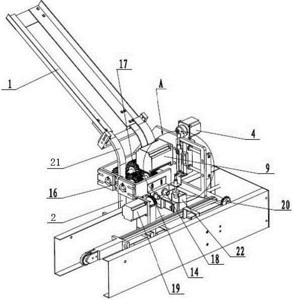
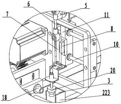
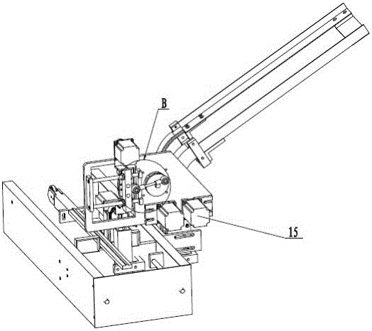
[0021] As shown in the figure, a blanking device of a knife, fork, and spoon packaging machine includes a discharge guide rail 1, a discharge guide rail 2, a feeding mechanism, and a conveying mechanism. The discharge guide rail 1 is used to place materials, discharge materials The guide rail 1 is rectangular, the feeding guide rail 2 is connected with the discharging guide rail 1, and the feeding mechanism is used to push the material to feed along the feeding guide rail 2, and the feeding guide rail 2 includes an arc-shaped transition portion 21 And the material guide portion 22, the material guide portion 22 is U-shaped, including a first vertical portion 221, an arc-shaped bending portion 222 and a second vertical portion 223, and the arc-shaped transition portion 21 is opposite to the discharge guide rail 1 Next, the arc-shaped bending portion 222 is located at the bottom to con...


PUM


Abstract

The invention relates to an unloading device of a knife, fork and scoop packing machine, which mainly solves the problems of the existing catering tool that multiple materials are unloaded and the package is affected when in unloading. The unloading device comprises a discharge guide rail, an unloading guide rail, a feeding mechanism and a conveying mechanism, wherein the discharge guide rail is used for storing a material, the unloading guide rail is connected with the discharge guide rail, the feeding mechanism is used for pushing the material to be fed along the unloading guide rail, the unloading guide rail comprises an arc transitional part and a guide part, the guide part is in a U shape and comprises a first vertical part, an arc curved part and a second vertical part, the arc transitional part is in butt joint with the discharge guide rail, the bottom of the curved part is connected with the first vertical part and the second vertical part, the first vertical part is in abut joint with the arc transitional part, and an opening is formed in the end part of the second vertical part. By adopting an unloading-after-loading continuous unloading way, the affection of the gravity and an acting force between two adjacent materials can be avoided, the phenomenon that multiple materials are simultaneously dropped can be effectively avoided, stability in unloading is realized, and the structure is reasonable.

Description

technical field [0001] The invention relates to a packaging device for catering utensils, in particular to a cutting device for a knife, fork and spoon packaging machine. Background technique [0002] At present, it is used on the packaging machine used in the packaging production of catering tools such as knives, forks, and spoons on the market. The packaging machine includes steps such as blanking and packaging. In the unloading step, the material is placed in the feeding trough, and the material is pushed down by the roller brush. The feeding direction of the material is from the top to the bottom, or the material is discharged in an inclined downward direction. Due to the influence of gravity, And when the bonding between adjacent materials does not match or is misplaced, it is easy for multiple materials to fall at the same time when unloading. When packaging, only one knife, fork, spoon and other materials are allowed to come down, and then the positioning and packagi...

Claims


Application Information

Patent Timeline
Patent Type & Authority Patents(China)
IPC IPC(8): B65B35/10
CPCB65B35/10B65B35/18B65B57/20
Inventor 朱向东朱云锋
Owner PINGYANG HAIHANG MACHINERY
Learn More