
Bionic knee joint

A technology of knee joint and prosthesis is applied to the bionic knee joint. It can solve the problems of lack of stability and backwardness of prosthetics

Inactive Publication Date: 2015-06-03
UNIV OF SHANGHAI FOR SCI & TECH
View PDF4 Cites 15 Cited by
  • Summary
  • Abstract
  • Description
  • Claims
  • Application Information

AI Technical Summary

Problems solved by technology

However, the current level of domestic intelligent prosthetics is relatively backward compared with foreign countries, and the movement of the prosthetics also lacks certain stability. Therefore, from the perspective of biomechanics, anatomy and physiology, the gait movement law and force of the knee joint during walking are analyzed. Features and Physiological Functions

Method used


Image

  • Bionic knee joint
  • Bionic knee joint
  • Bionic knee joint

Examples


Embodiment Construction

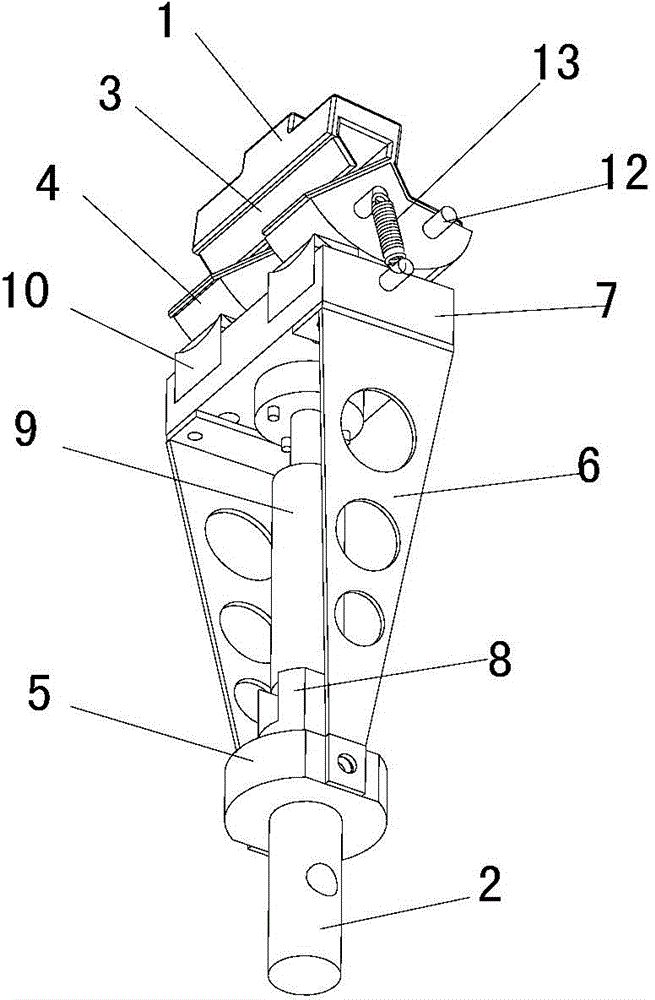
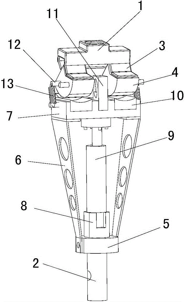
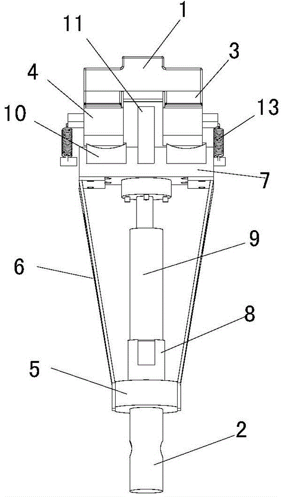
[0030] see figure 1 , with reference to figure 2 , image 3 , Figure 4 , the bionic knee joint of the present invention is used to be connected between the thigh prosthesis and the calf prosthesis, comprising a femoral connector 1 for being connected with the thigh prosthesis, and a tibial connector 2 for being connected with the calf prosthesis, between the femoral connector and the calf prosthesis Between the tibial connectors are: femoral condyle positioning block 3, a pair of femoral condyles 4, tibial plateau support mounting seat 5, two tibial plateau support 6, tibial condyle fixing platform 7, damper mounting seat 8, and cylinder damper 9 , a pair of tibial condyles 10, a joint movement guide block 11, a guide rod 12 and a pair of ligament models 13.

[0031] Wherein, the femoral condyle positioning block 3 is connected with the femoral connector 1; a pair of femoral condyle 4 is fixedly connected with the femoral condyle positioning block 3 respectively; the tibi...


PUM


Abstract

The invention provides a bionic knee joint which is connected between an artificial thigh and an artificial crus. The bionic knee joint comprises a thighbone connecting part which is connected with the artificial thigh, and a tibia connecting part which is connected with the artificial crus; a femoral condyle positioning block, a pair of femoral condyle and tibia platform bracket mounting seats, two tibia platform brackets, a tibial condylar fixing platform, a damper mounting seat, a cylinder damper, a pair of tibial condylar and joint movement guide blocks, a guide rod and a pair of ligament models are arranged between the thighbone connecting part and the tibia connecting part. According to the bionic knee joint, the knee joint structure is simplified, a guide mechanism is constructed by analyzing the kinematics characteristics of the knee joint, and therefore, the functions of the knee joint are achieved, and the bionic knee joint has the advantages of being pliable, flexible, stable and light.

Description

technical field [0001] The invention relates to a bionic device, in particular to a bionic knee joint. Background technique [0002] In today's society, due to various reasons, one of the most basic functions of human beings has been lost - the number of people walking upright has been increasing, which undoubtedly brings great inconvenience to their lives. However, the advent of artificial legs (prosthetics) has solved their pain spiritually. With the development of science and technology, the structure and function of artificial legs have also been further improved. But this is always a concept of a mechanical device, and most of them are follow-up products, which lack the unique functions of human muscles. Walking that deviates from human legs is a joint movement of active force-inertial force-damping force result. [0003] The bionic intelligent knee joint is one of the important achievements in the development of artificial limb technology in recent years. At presen...

Claims


Application Information

Patent Timeline
Patent Type & Authority Applications(China)
IPC IPC(8): A61F2/64
Inventor 赵改平王晨曦柏磊磊方新果尚昆
Owner UNIV OF SHANGHAI FOR SCI & TECH
Learn More