
LED dimming circuit and LED lamp

A technology of a dimming circuit and a dimming switch, which is applied in the field of LED lighting, and can solve problems such as the inability of segmented dimming to be universal and so on.

Active Publication Date: 2015-05-27
SHENZHEN JBT SMART LIGHTING
View PDF6 Cites 4 Cited by
  • Summary
  • Abstract
  • Description
  • Claims
  • Application Information

AI Technical Summary

Problems solved by technology

Its advantage is that it can realize stepless dimming, but it cannot be used in common with segmental dimming.

Method used


Image

  • LED dimming circuit and LED lamp
  • LED dimming circuit and LED lamp

Examples


Embodiment Construction

[0012] In order to make the technical problems, technical solutions and beneficial effects to be solved by the present invention clearer, the present invention will be further described in detail below in conjunction with the accompanying drawings and embodiments. It should be understood that the specific embodiments described here are only used to explain the present invention, not to limit the present invention.

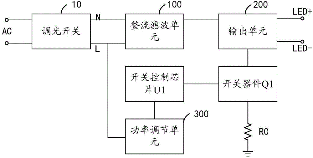
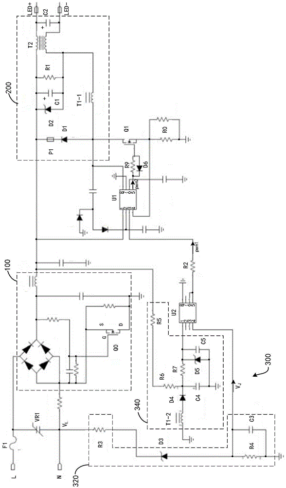
[0013] see figure 1 and figure 2 , the LED dimming circuit in the LED lamp in the preferred embodiment of the present invention, that is, the switching power supply, the LED dimming circuit is respectively connected to the output terminal L of the dimming switch 10 and the neutral line output terminal N, and the LED dimming circuit includes The rectification and filtering unit 100 , the switch device Q1 , the switch control chip U1 , the output unit 200 , the sampling resistor R0 and the power adjustment unit 300 . The switch control chip U1 is a power controlle...


PUM


Abstract

The invention provides an LED lamp. The LED lamp comprises an LED dimming circuit connected with a diming switch, wherein the LED dimming circuit comprises a rectifying and filtering unit, a switch device, a switch control chip, an output unit, a sampling resistor and a power regulating unit; the power regulating unit is used for collecting waveform of output voltage of the output end of the diming switch; when the waveform is a normal sine wave, the output power of the output unit is regulated according to switching on and off frequency of the output voltage with accordance with the condition; when the waveform is a chopped sine wave, the output power of the output unit is regulated to be maximum. The LED dimming circuit is used for detecting the current waveform which passes through regulation switches and judging the type of the regulation switches according to the characteristics of different influences of ordinary switches and silicon-controlled regulation switches on the current, thereby controlling output power of the circuit by using different control strategies and implementing compatibility of stepless dimming and segmental dimming.

Description

technical field [0001] The invention relates to LED lighting technology, in particular to an LED dimming circuit and an LED lamp. Background technique [0002] In the existing segmental dimming, a common wall switch is used to generate corresponding output power and brightness through different switching times. The circuit is implemented by using a functional circuit that can identify the number of times the switch is turned on, so that the circuit generates a corresponding output power to make the LED lamp emit different brightness. But its weakness is that the dimming is segmented, usually only 2 to 4 segments, and the brightness cannot be adjusted linearly. The advantage is that it is simple to use and install. [0003] Existing thyristor dimming requires a special thyristor dimmer and a special power supply or light source with thyristor dimming function to cooperate with it. Its advantage is that it can realize stepless dimming, but it cannot be used in common with s...

Claims


Application Information

Patent Timeline
Patent Type & Authority Applications(China)
IPC IPC(8): H05B37/02
CPCY02B20/40
Inventor 张文彬胡鸿生郭光立谭世昌
Owner SHENZHEN JBT SMART LIGHTING
Learn More