
Voltage regulation device of mixed excitation direct-current generator and voltage regulation method of mixed excitation direct-current generator

A DC generator and mixed excitation technology, which is applied in the direction of controlling the generator through the change of the magnetic field, controlling the generator, synchronous generator control, etc., can solve the problems such as the performance degradation of the generator that cannot be changed, and the poor dynamic performance.

Active Publication Date: 2015-05-27
智驱机电科技(常州)有限公司
View PDF4 Cites 8 Cited by
  • Summary
  • Abstract
  • Description
  • Claims
  • Application Information

AI Technical Summary

Problems solved by technology

At the same time, in the past, most of the excitation regulators of generators used ordinary output voltage feedback plus excitation current feedforward control methods, and the control loop adjustment was still PI control, with poor dynamic performance.
At the same time, this control method cannot change the performance degradation of the generator caused by the change of the generator parameters due to the change of the ambient temperature and other factors.

Method used


Image

  • Voltage regulation device of mixed excitation direct-current generator and voltage regulation method of mixed excitation direct-current generator
  • Voltage regulation device of mixed excitation direct-current generator and voltage regulation method of mixed excitation direct-current generator
  • Voltage regulation device of mixed excitation direct-current generator and voltage regulation method of mixed excitation direct-current generator

Examples


Embodiment Construction

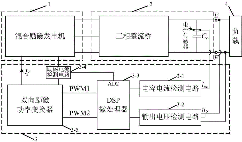
[0053] like figure 1 As shown, a hybrid excitation DC generator device includes a hybrid excitation generator (1), an AC / DC conversion circuit (2), a bidirectional excitation regulator (3) and a load circuit (4); the hybrid excitation generator ( 1) A, B, and C three-phase voltage output terminals are electrically connected to the input terminals of the AC-DC conversion circuit (2), and the DC output of the AC-DC conversion circuit (2) is connected to the load circuit (4), and the The output terminal of the three-phase rectifier bridge in the AC-DC conversion circuit (2) and the filter capacitor C o It is electrically connected to the corresponding connection end of the excitation regulator (3), and the connection end of the excitation winding of the hybrid excitation generator (1) is electrically connected to the corresponding connection end of the excitation regulator (3).

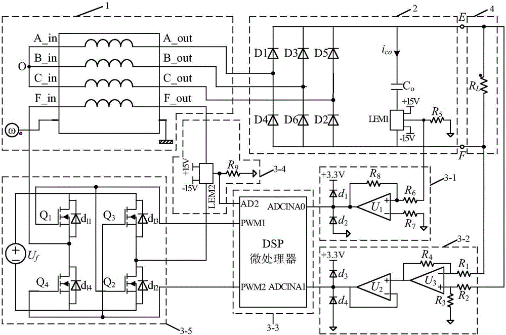
[0054] like figure 2 As shown, the AC-DC conversion circuit (2) includes a three-phase rectifier bri...


PUM


Abstract

The invention discloses a voltage regulation device of a mixed excitation direct-current generator and a voltage regulation method. The device comprises a mixed excitation generator, an alternating-current / direct-current switching circuit, a bidirectional excitation regulator and a load circuit, wherein an A-phase voltage output end, a B-phase voltage output end and a C-phase voltage output end of the mixed excitation generator are electrically connected with an input end of the alternating-current / direct-current switching circuit; direct-current output of the alternating-current / direct-current switching circuit is connected to the load circuit; an output end of a three-phase rectifier bridge and a filter capacitor Co in the alternating-current / direct-current switching circuit are electrically connected with corresponding connecting ends of the excitation regulator; an excitation winding connecting end of the mixed excitation generator is electrically connected with the corresponding connecting end of the excitation regulator. The circuit structure is simple, the production cost is lower, the device has fast dynamic response and can obtain better dynamic property, and output voltage static difference during generation is reduced.

Description

technical field [0001] The invention specifically relates to a hybrid excitation direct current generator voltage regulating device and a voltage regulating method thereof. Background technique [0002] In recent years, in order to combine the advantages of high efficiency of permanent magnet motors and easy magnetic field adjustment of electric excitation motors, many motor experts have proposed hybrid excitation motors, that is, motors have two sources of magnetic potential, namely permanent magnets and electric excitation magnetic potentials. When the hybrid excitation motor is used as a generator, the generator can obtain a wider power generation operating speed range and demagnetization protection capability under the condition that the efficiency does not drop much. However, as a new type of hybrid excitation generator, its excitation regulator needs to have the ability to adjust the excitation current bidirectionally, that is, the excitation current can be adjusted bo...

Claims


Application Information

Patent Timeline
IPC IPC(8): H02P9/30H02P103/20
CPCH02P9/307H02P2205/01
Inventor 戴卫力丁骏田浩
Owner 智驱机电科技(常州)有限公司
Learn More