Rotor Of Rotary Motor

A technology for rotating electrical machines and rotors, applied in the field of rotors of rotating electrical machines, can solve the problems of inability to set up ventilation ducts, loss of mechanical strength, noise, and lack of ventilation ducts.

Inactive Publication Date: 2015-05-27
TOSHIBA MITSUBISHI-ELECTRIC IND SYST CORP
View PDF7 Cites 2 Cited by
  • Summary
  • Abstract
  • Description
  • Claims
  • Application Information

AI Technical Summary

Problems solved by technology

[0003] However, for rotating electric machines such as large-capacity induction motors with a rotational speed of 3,600 rpm or more, if radial ventilation ducts are provided on the rotor core, there will be problems in terms of mechanical strength, loss, noise, etc., so ventilation cannot be provided. Ducts, becoming structures without ventilation ducts

Method used


Image

  • Rotor Of Rotary Motor
  • Rotor Of Rotary Motor

Examples


Embodiment Construction

[0008] Embodiments of the present invention will be described in detail below in conjunction with the accompanying drawings.

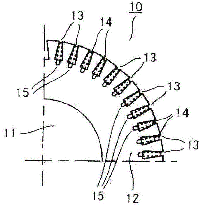
[0009] figure 1 shows the rotor 10 of the rotating electrical machine of this embodiment, figure 2 1 / 4 of the cross section of the rotor 10 is shown.

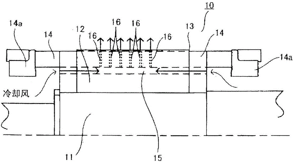
[0010] exist figure 1 and figure 2 Among them, the rotor 10 is constituted by fitting and mounting a rotor core 12 on the outer peripheral surface of a rotating shaft 11 . On the outer peripheral surface of the rotor core 12, figure 1 The illustrated plurality of slots 13 are respectively formed in the axial direction, and the rotor rods 14 are respectively accommodated in these slots 13 . Both ends of these rotor bars 14 are connected to each other by end rings 14a.

[0011] In addition, on the rotor core 12, the ventilation slots 15 slotted at the bottom of the plurality of slots 13 are respectively formed along the length direction of the corresponding slots 13, as figure 1 As shown, their b...


PUM


Abstract

The present invention relates to a rotor of a rotary motor of which the ventilation cooling structure is improved. The ventilation cooling can be carried out effectively on the rotor rods without arranging a radial ventilation channel on a rotor iron core. The rotor (10) of the rotary motor is equipped with a plurality of cutting grooves (13) for accommodating the rotor rods (14) respectively along an axial direction and on the peripheral surface of the rotor iron core (12) embedded and arranged on a rotating shaft (11). On the rotor iron core (12), the ventilation grooves (15) at the bottoms of the cutting grooves (13) are formed along the length directions of the corresponding cutting grooves (13), a plurality of ventilation holes (16) are arranged on the rotor rods (14), one ends of the ventilation holes (16) face the ventilation grooves (15), and the other ends are communicated with the groove parts of the cutting grooves (13).

Description

technical field [0001] Embodiments of the present invention relate to a rotor of a rotating electric machine in which a ventilation cooling structure is improved. Background technique [0002] In the rotor of a rotating electric machine such as an induction motor, a rotor core is fitted to an outer peripheral surface of a rotating shaft, and a plurality of slots are formed in the axial direction on the outer peripheral surface of the rotor core. And the rotor rods are respectively accommodated in these slots. This type of rotating electrical machine generates heat during operation, so in order to prevent its temperature from rising, ventilation cooling is required. As the ventilation and cooling structure of the rotor, as described in Japanese Patent Application Laid-Open No. 11-150898, radial ventilation ducts are generally arranged at multiple axial positions of the cylindrical rotor core, so that the inflow passes through the rotor in the axial direction. The cooling ai...

Claims


Application Information

Patent Timeline
Patent Type & Authority Applications(China)
IPC IPC(8): H02K1/32
CPCH02K1/32
Inventor 刘克成小西和成森宁
Owner TOSHIBA MITSUBISHI-ELECTRIC IND SYST CORP
Why Eureka
Try Eureka