Electrical zero positioning device for optical fiber observation unit of multiple-target telescope

A positioning device and telescope technology, applied in position/direction control, non-electric variable control, instruments, etc., can solve the problem that the accumulated error cannot be eliminated, and achieve the effects of simple structure, extended precision life, and high positioning accuracy

Inactive Publication Date: 2015-05-27
DALIAN WEIKANG TECH
View PDF1 Cites 0 Cited by
  • Summary
  • Abstract
  • Description
  • Claims
  • Application Information

AI Technical Summary

Problems solved by technology

But because there is no zero positioning device, the cumulative error cannot be eliminated

Method used


Image

  • Electrical zero positioning device for optical fiber observation unit of multiple-target telescope
  • Electrical zero positioning device for optical fiber observation unit of multiple-target telescope
  • Electrical zero positioning device for optical fiber observation unit of multiple-target telescope

Examples


Embodiment Construction

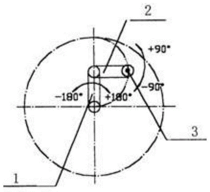
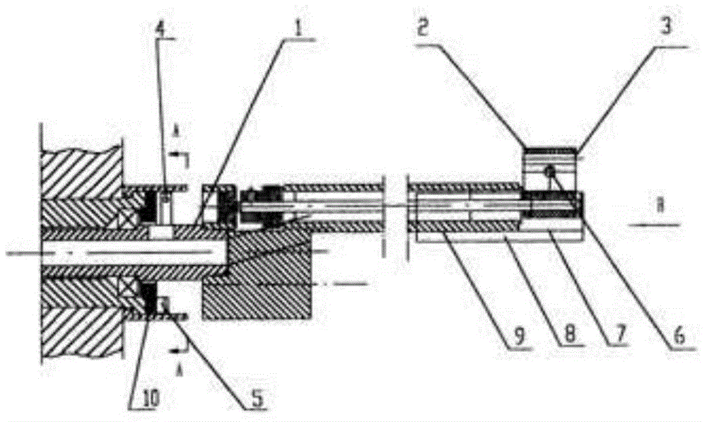
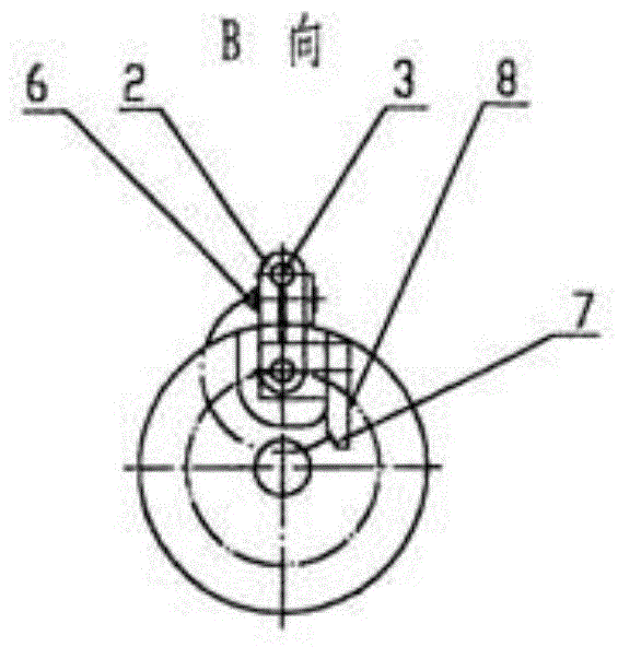
[0019] Such as Figure 1 to Figure 6 Shown: below in conjunction with accompanying drawing and embodiment the structure of the present invention is described in detail. Among them, the eccentrically rotating static contact 7 is set on the axial stopper 8 on the head of the observation unit, the axial stopper is fixed on the eccentric sleeve 9, and the eccentrically rotating movable contact 6 is set on the eccentrically rotating arm 2 on the optical fiber head Inside of 3; the central rotating static contact 5 is set on the central zero retaining ring 10 in the middle of the observation unit, and the movable contact 4 is installed on the central rotating arm 1, which is in the same section as the static contact 5. The controller 12 adopts an 8051 single-chip microcomputer system, the stepper motor 11 adopts a Swiss ASPAR12-250 motor, and the value of the current-limiting resistor R is 1K.


PUM


Abstract

The invention discloses an electrical zero positioning device for an optical fiber observation unit of a multiple-target telescope. According to the electrical zero positioning device, electric control components, i.e., a movable contact, a stationary contact, a corresponding controller and the like, are additionally arranged in a double-slewing mechanism of the existing optical fiber observation unit. The movable contact is arranged on a slewing arm; the stationary contact is arranged on a slewing circle of the movable contact; the movable contact and the stationary contact are connected with a low level end and a high level end in the controller; a driving output end of the controller is connected with an input end of a slewing arm driving motor; and operation of the driving motor is controlled by a pulse signal of the controller. The device can eliminate a cumulative error generated by the optical fiber observation unit in a continuous observation process and is higher in positioning accuracy. At the same time, the device further has the characteristics of simple structure and very small size, so that mechanical deadlock cannot be generated, and the motion of the optical fiber observation unit cannot be affected.

Description

technical field [0001] The invention relates to an electrical zero position positioning device for a multi-objective telescope optical fiber observation unit. Background technique [0002] The Multi-Object Telescope (LAMOST for short) is a telescope used to observe multiple star phases at the same time, and has a fiber optic observation unit for each star phase. In the past, the positioning of each star phase (that is, each optical fiber observation unit) was manually inserted. Patent No. 98246662.5 proposes an optical fiber observation unit with a double-turn mechanism, which can automatically switch the observation target. But because there is no zero positioning device, the accumulated error cannot be eliminated. Contents of the invention [0003] The object of the present invention is to provide an electrical zero position positioning device for the optical fiber observation unit of a multi-objective telescope, which can eliminate cumulative errors and has high posit...

Claims


Application Information

Patent Timeline
Patent Type & Authority Applications(China)
IPC IPC(8): G05D3/00
Inventor 鞠洪建
Owner DALIAN WEIKANG TECH
Why Eureka
Try Eureka