
Dedicated mold for testing electrical property of lithium iron phosphate

A lithium battery and iron phosphate technology, applied in the field of new energy material testing, can solve problems such as unsatisfactory result consistency, large errors, and difficulties, and achieve the effects of saving test costs, reducing test result errors, and improving consistency

Inactive Publication Date: 2015-05-27
吴坚
View PDF0 Cites 4 Cited by
  • Summary
  • Abstract
  • Description
  • Claims
  • Application Information

AI Technical Summary

Problems solved by technology

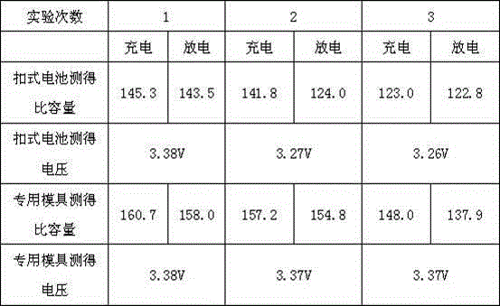
[0003] However, even in the form of a button battery, there are still certain defects: on the one hand, the button battery can only be used once, and after the test of a button battery is completed, it can only be discarded entirely. The long-term accumulation of cost is also very considerable; on the other hand, due to the shape characteristics of the positive and negative electrodes of the button battery, the two ends of the button battery must be completely pressed during the test, but it must be 100% every time. Contact compression is very difficult. When charging and discharging tests, there is often a certain amount of air in the plane gaps, which leads to unsatisfactory consistency of test results and large errors.

Method used


Image

  • Dedicated mold for testing electrical property of lithium iron phosphate
  • Dedicated mold for testing electrical property of lithium iron phosphate
  • Dedicated mold for testing electrical property of lithium iron phosphate

Examples


Embodiment Construction

[0018] The present invention will be described in further detail below according to the drawings and embodiments.

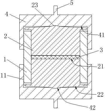
[0019] Such as figure 2 As shown, a special mold for lithium iron phosphate electrical testing described in the embodiment of the present invention includes: an insulating sleeve 1, the insulating sleeve 1 has a through hole, and the outer two ends of the insulating sleeve 1 are respectively provided with external threads 11; The conductive pressure block 2 at both ends of the insulating sleeve 1 is used to fill the lithium iron phosphate powder 3 between the two conductive pressure blocks 2; the conductive shell 4 installed at both ends of the insulating sleeve 1, the conductive shell 4 has an external thread 11 With matching internal threads, the inner wall 41 of the conductive housing 4 abuts against and compresses the conductive compression block 2 .

[0020] In order to better contact the lithium iron phosphate, the opposite end surfaces 21 of the two cond...


PUM


Abstract

The invention relates to a dedicated mold for testing the electrical property of lithium iron phosphate. The dedicated mold comprises an insulating sleeve, two conducting compressing blocks and conducting housings, wherein the conducting compressing blocks are inserted into two ends of the insulating sleeve; the conducting housings are mounted at the two ends of the insulating sleeve; the space between the conducting compressing blocks is filled with lithium iron phosphate powder; a through hole is formed in the insulating sleeve; external threads are formed in two external ends of the insulating sleeve; inner threads matched with the external threads are formed in the conducting housings; the inner walls of the conducting housings are propped against and compress the conducting compressing blocks. Before tests, one conducting compressing block and one conducting housing are mounted at one end of the insulating sleeve, the insulating sleeve is uniformly filled with the lithium iron phosphate powder, and then the other conducting compressing block and the other conducting housing are mounted, so that the button cell utilized in the conventional charging and discharging tests can be replaced, and the test cost can be reduced; the conducting compressing blocks can get in direct and sufficient contact with lithium iron phosphate, so that the test data consistency of the lithium iron phosphate charging and discharging tests can be improved, and errors in the test results can be reduced.

Description

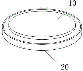
technical field [0001] The invention relates to a special mold for testing the electric properties of lithium iron phosphate, which belongs to the technical field of testing new energy materials. Background technique [0002] In the prior art, after lithium battery material manufacturers produce lithium battery materials, they usually use charge and discharge tests to detect the performance of lithium battery materials, such as the detection of charge and discharge cycle performance of lithium iron phosphate powder. In traditional charge and discharge tests, as The preferred solution in the prior art generally needs to make lithium iron phosphate into a button battery in advance, such as figure 1 As shown, the appearance structure of the button battery generally uses lithium iron phosphate cathode material as the anode 10, metal lithium sheet as the anode 20, and also includes an internal electrolytic medium (not shown). It should be said that the current industry uses butto...

Claims


Application Information

Patent Timeline
Patent Type & Authority Applications(China)
IPC IPC(8): G01R31/36
Inventor 杭艳杨柯许世国肖立群
Owner 吴坚
Learn More