
Cogging-torque test method for alternating-current permanent-magnet synchronous servo motor

A servo motor, cogging torque technology, applied in torque measurement, measurement device, power measurement and other directions, can solve the problems of low precision and large error, and achieve the effect of simple and convenient use

Inactive Publication Date: 2015-05-27
PHASE MOTION CONTROL NINGBO
View PDF5 Cites 10 Cited by
  • Summary
  • Abstract
  • Description
  • Claims
  • Application Information

AI Technical Summary

Problems solved by technology

[0006] The technical problem to be solved by the present invention is to provide a cogging torque test method for AC permanent magnet synchronous servo motors to solve the problems of low precision and large errors in existing test methods

Method used


Image

  • Cogging-torque test method for alternating-current permanent-magnet synchronous servo motor

Examples


Embodiment 1

[0019] A method for testing the cogging torque of an AC permanent magnet synchronous servo motor, the specific measurement method is as follows:

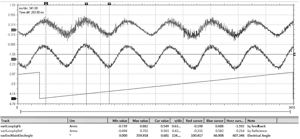
[0020] 1. First connect the motor under test, driver and encoder, and then zero-adjust the encoder. 2. Test the back electromotive force of the motor and calculate the current torque constant Kt. 3. Set the relevant control parameters of the driver, rotate the motor, and continuously adjust the parameters so that the motor can run stably at no-load and low speed. 4. Set the speed of the motor under test to a lower speed of 1 to 5 rpm. 5. Use the analog oscilloscope module that comes with the driver software to collect the electrical angle and feedback current waveform of the motor in real time. 6. By analyzing and calculating the current waveforms in multiple electrical cycles, the cogging torque is obtained.

[0021] Such as figure 1 As shown, the abscissa is time, and the waveforms of the ordinate are electrical angle, referen...


PUM


Abstract

The invention relates to a cogging-torque test method for an alternating-current permanent-magnet synchronous servo motor. According to the cogging-torque test method, a servo driver is utilized to drive a tested motor to stably rotate at a lower rotating speed, an encoder is utilized to detect the speed and the position information of the motor, and the cogging torque of the motor can be tested through the combination of recorded feedback currents at different positions with the torque constant of the electric current. According to the cogging-torque test method disclosed by the invention, no special tool or work equipment needs to be prepared, all that is needed is to connect the motor with the driver and regulate the control parameters to proper values, so that the motor can stably run at a lower rotating speed, then data can be acquired, and the cogging torque can be calculated; the cogging-torque test method is simple and convenient in usage.

Description

technical field [0001] The invention belongs to the technical field of motors, in particular to a method for testing the cogging torque of an AC permanent magnet synchronous servo motor. Background technique [0002] Cogging torque is an inherent phenomenon of permanent magnet motors. It is the torque generated in the circumferential direction by the interaction between the permanent magnet magnetic field and the cogging of the armature core when the motor winding is not energized. It is constant and relative to the rotor position. The cogging torque will cause the permanent magnet motor to generate vibration and noise during operation, and transmit the pulsating torque to the load through the rotating shaft, reducing the speed and position control accuracy of the system, and this phenomenon is especially obvious at low speeds. Scholars at home and abroad have devoted a lot of energy to research how to suppress or eliminate cogging torque. And its accurate measurement is v...

Claims


Application Information

Patent Timeline
IPC IPC(8): G01L3/00
Inventor 牛正蕊周丹毕晨光檀已宇
Owner PHASE MOTION CONTROL NINGBO
Learn More