
Glass breaking device

A glass breaking and glass technology, applied in glass recycling, recycling technology, grain processing, etc., to save manpower and improve work efficiency

Inactive Publication Date: 2015-05-27
HEFEI XINSHENG OPTOELECTRONICS TECH CO LTD +1
View PDF6 Cites 5 Cited by
  • Summary
  • Abstract
  • Description
  • Claims
  • Application Information

AI Technical Summary

Problems solved by technology

Improve work efficiency

Method used


Image

  • Glass breaking device
  • Glass breaking device
  • Glass breaking device

Examples


Embodiment Construction

[0033] The features and principles of the present invention will be described in detail below with reference to the accompanying drawings, and the examples given are only used to explain the present invention, not to limit the protection scope of the present invention.

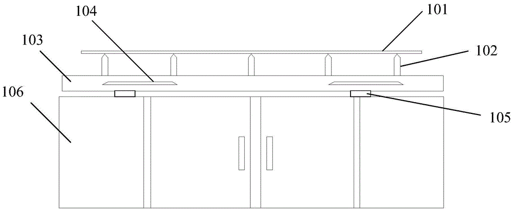
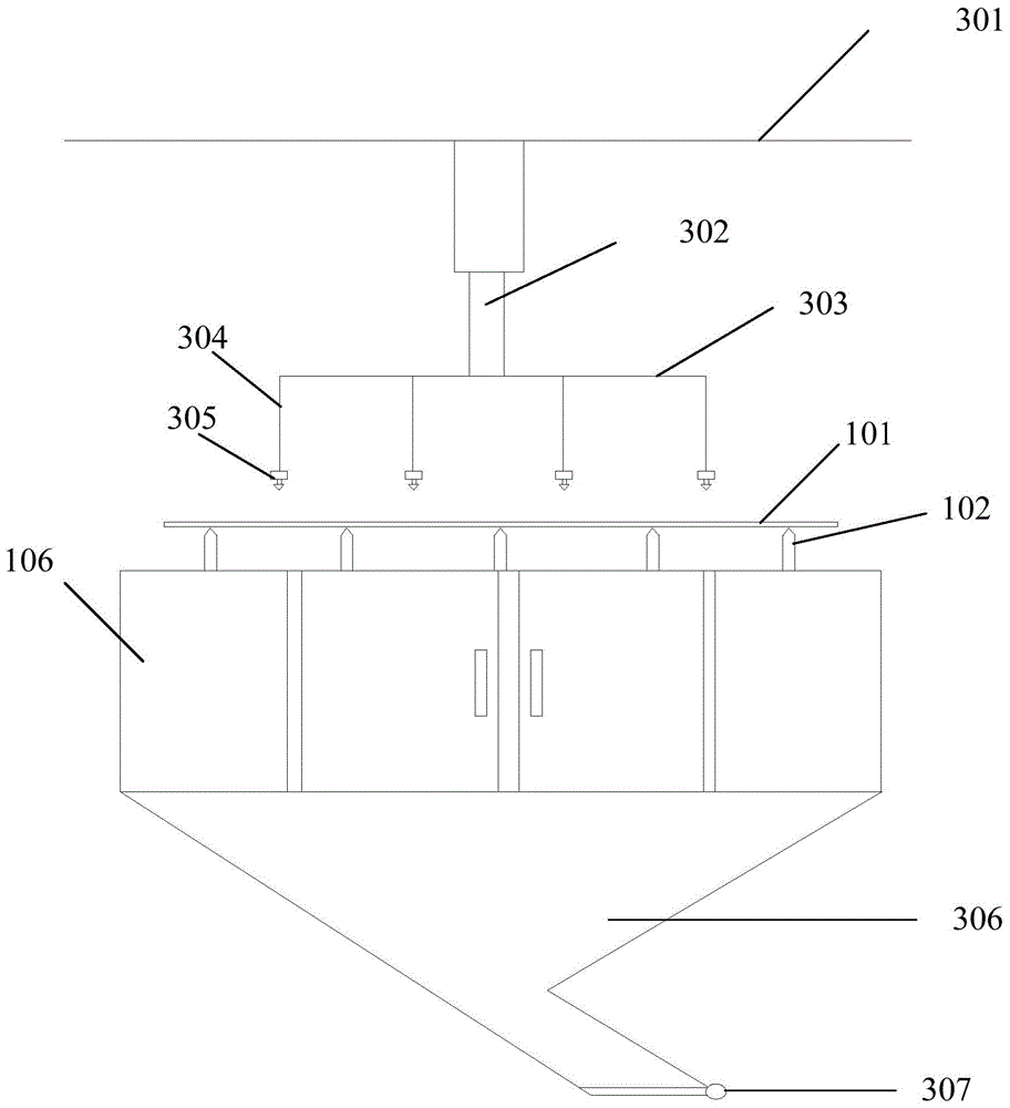
[0034] like figure 2 Shown, a kind of glass crushing device comprises:

[0035] a glass carrying unit for carrying glass;

[0036] a glass breaking unit, arranged above the glass, for breaking glass;

[0037] The control unit is used to control the glass breaking unit to move towards or away from the glass.

[0038] The intelligent mechanical device realizes the function of automatically breaking the glass, which saves manpower and improves operating efficiency and equipment utilization rate.

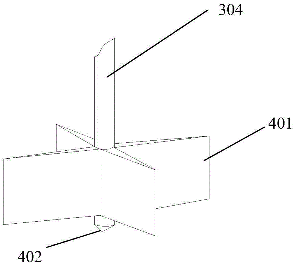
[0039] The specific structural forms of the glass breaking unit can be various, as long as the glass can be broken. In this embodiment, the glass breaking unit includes:

[0040] Strike parts for breaking glass;

...


PUM


Abstract

The invention relates to a glass breaking device which comprises a glass bearing unit, a glass breaking unit and a control unit, wherein the glass bearing unit is used for bearing the glass; the glass breaking unit is arranged above the glass and is used for breaking the glass; and the control unit is used for controlling the glass breaking unit to move to the direction close to or far away from the glass. The glass breaking device disclosed by the invention has the beneficial effects that automatic control of glass breaking is realized, the manual labor is saved, and the working efficiency is improved.

Description

technical field [0001] The invention relates to the technical field of liquid crystal display manufacture, in particular to a glass breaking device. Background technique [0002] In the box-forming process of liquid crystal panels, the Rubbing (rubbing) process refers to rubbing the surface of the alignment film on the substrate with a certain direction and force with a Roller (roller) wrapped in nylon cloth or cotton cloth, so that it can form a liquid crystal Grooves with alignment and predicted angles, this process is called liquid crystal molecular alignment technology. The Scrap Buffer (broken buffer) device in the Rubbing process is used to buffer the Glass (glass) that needs to be scrapped. During the production process of the Rubbing process or the Glass tape-out process, occasionally some defective Glass with abnormal incoming materials will occur. It has been confirmed It needs to be scrapped. At this time, these Glasses need to be put into the Scrap Buffer device...

Claims


Application Information

Patent Timeline
IPC IPC(8): B02C19/00B02C25/00
CPCY02W30/60B02C19/0056B02C25/00
Inventor 王文浩洪艳平黄助兵余鹏阮德发张超
Owner HEFEI XINSHENG OPTOELECTRONICS TECH CO LTD
Learn More