
Combined antenna selection method for spatial phase modulation

An antenna selection and spatial phase technology, applied in the field of communication anti-jamming, can solve the problems of high complexity of antenna selection, the combination of transmitter and receiver, and achieve the effect of improving communication reliability, low complexity, and reducing BER

Inactive Publication Date: 2015-05-20
UNIV OF ELECTRONICS SCI & TECH OF CHINA
View PDF5 Cites 7 Cited by
  • Summary
  • Abstract
  • Description
  • Claims
  • Application Information

AI Technical Summary

Problems solved by technology

[0006] The present invention provides a joint antenna selection method for spatial phase modulation, which is used to solve the shortcomings of high antenna selection complexity and the inability to perform joint antenna selection at the transmitting end and the receiving end in the prior art

Method used


Image

  • Combined antenna selection method for spatial phase modulation
  • Combined antenna selection method for spatial phase modulation

Examples


Embodiment Construction

[0028] The technical solution of the present invention will be described in detail below in combination with the embodiments and the accompanying drawings.

[0029] In order to describe the present invention better, the terms used in the technical solution of the present invention and the transmitter structure of the spatial modulation system are introduced first.

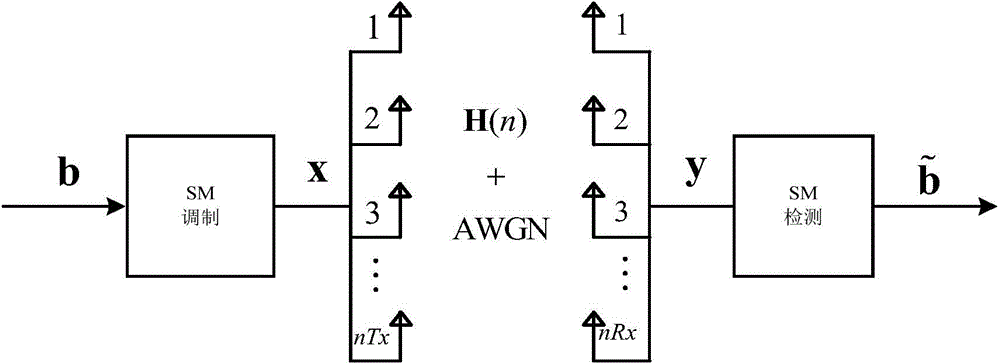
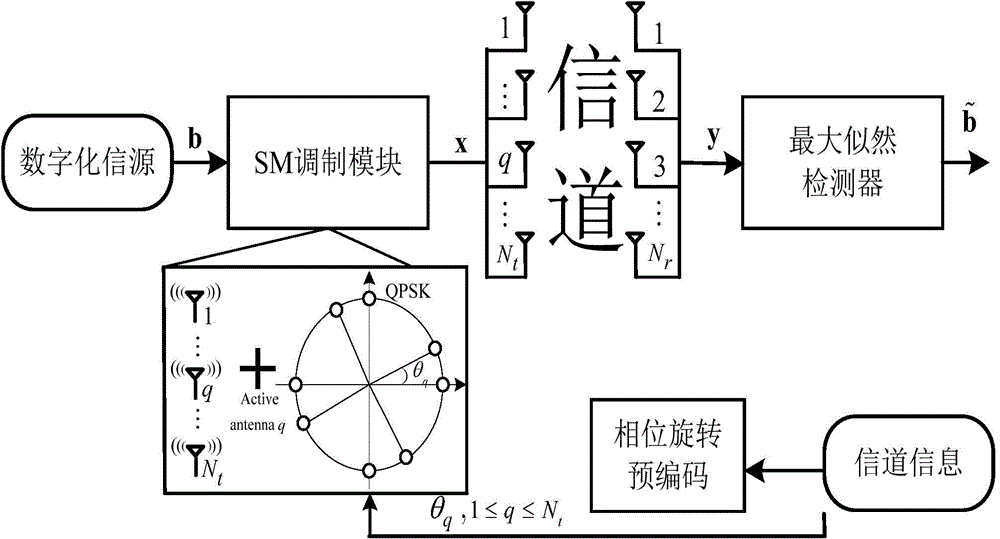
[0030] Spatial modulation: eg figure 1 As shown, b is the bit data that needs to be transmitted, and can be regarded as a matrix of L×T, wherein, L=log2(M)+log2(Mary) is the number of bits carried by an SM modulation symbol, and Mary is an orthogonal Amplitude modulation (Quadrature Amplitude Modulation, QAM) order. It can be seen that the number of bits that can be carried by one SM modulation symbol is jointly determined by the QAM modulation order and the number of transmit antennas. The SM modulation criterion is to convert b into an M×T matrix x according to the SM conversion table. In x, one column represe...


PUM


Abstract

The invention belongs to the technical field of communication anti-jamming, and particularly relates to a spatial modulation (SM) technology, an antenna selection technology and a multiple input and multiple output (MIMO) modulation technology. An antenna selection method is mainly characterized in that a receiving end obtains an optimal transmitting antenna set and an optimal receiving antenna set according to an estimated channel matrix H. According to the estimated channel matrix in a receiver, receiving antennas are used for receiving in sequence. When each receiving antenna is selected and activated respectively, the sum of transmitting antennas with the maximum module values is taken as the transmitting antenna set according to the transmitting antennas with the maximum module values in required number. After selection of the transmitting antennas, the transmitting antennas are required to be positioned on each receiving antenna, and a certain number of receiving antennas with the maximum module values is put into the receiving antenna set according to the module value sum of a channel coefficient. The antenna selection method is based on the thought of system capacity maximization at the cost of little increase in complexity, the BER (Bit Error Rate) of a system is effectively lowered, and the communication reliability of the system is enhanced.

Description

technical field [0001] The invention belongs to the technical field of communication anti-jamming, and in particular relates to spatial modulation (Spatial Modulation, SM) technology, antenna selection technology (Antenna Selection) and multiple input multiple output (Multiple Input Multiple Output, MIMO) modulation technology. Background technique [0002] MIMO modulation technology is a high-speed transmission technology in a wireless environment. This technology configures more wireless units at the transmitting end and / or receiving end, and combines advanced space-time coding modulation schemes to fully utilize the degree of freedom of space. , can bring additional diversity, multiplexing and beamforming gains, thereby improving the communication efficiency and reliability of the communication system. [0003] Recently, SM technology has been proposed as a new MIMO modulation scheme. The basic principle of this technology is to transmit information bits by activating di...

Claims


Application Information

Patent Timeline
Patent Type & Authority Applications(China)
IPC IPC(8): H04B7/06H04B7/08
Inventor 邵晋梁王宇肖悦尹露
Owner UNIV OF ELECTRONICS SCI & TECH OF CHINA
Learn More