
Data drive circuit, electric compensation method, array substrate and display device

A data drive circuit and data voltage technology, applied in static indicators, instruments, etc., can solve the problems of limited threshold voltage compensation effect and complicated TCON board design, achieve optimal compensation effect, reduce the number of use, and improve integration. Effect

Active Publication Date: 2015-05-20
BOE TECH GRP CO LTD
View PDF5 Cites 29 Cited by
  • Summary
  • Abstract
  • Description
  • Claims
  • Application Information

AI Technical Summary

Problems solved by technology

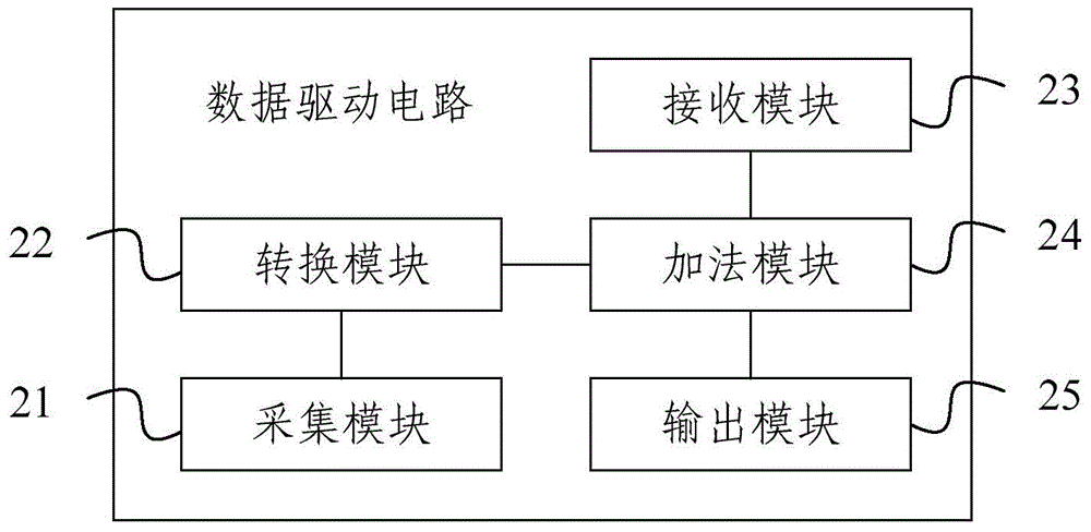
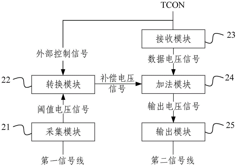
[0004] Aiming at the defects in the prior art, the present invention provides a data driving circuit, an electrical compensation method, an array substrate and a display device, which can solve the problem that the compensation effect of the threshold voltage of the internal circuit of the pixel is limited in the prior art, and the external circuit will cause TCON board design complex issues

Method used


Image

  • Data drive circuit, electric compensation method, array substrate and display device
  • Data drive circuit, electric compensation method, array substrate and display device
  • Data drive circuit, electric compensation method, array substrate and display device

Examples


Embodiment Construction

[0042] In order to make the purpose, technical solutions and advantages of the embodiments of the present invention clearer, the technical solutions in the embodiments of the present invention will be clearly and completely described below in conjunction with the drawings in the embodiments of the present invention. Obviously, the described embodiments It is a part of embodiments of the present invention, but not all embodiments. Based on the embodiments of the present invention, all other embodiments obtained by persons of ordinary skill in the art without creative efforts fall within the protection scope of the present invention.

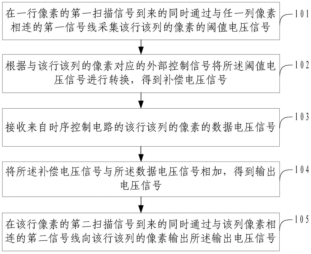
[0043] figure 1 It is a schematic flowchart of the steps of an electrical compensation method in an embodiment of the present invention. see figure 1 , the method includes:

[0044]Step 101: When the first scanning signal of a row of pixels arrives, the threshold voltage signal of the pixels in the row and column is collected through the first ...


PUM


Abstract

The invention provides a data drive circuit, an electric compensation method, an array substrate and a display device. The method comprises the steps: acquiring a threshold value voltage signal of pixel of a row and a column by virtue of a first signal wire connected to the row of pixels when a first scanning signal of the pixels is received; converting the threshold value voltage signal to obtain a compensation voltage signal according to an external control signal corresponding to the pixels of the row and the column; receiving a data voltage signal of the pixels of the row and the column from a time sequence control circuit; adding the compensation voltage signal together with the data voltage signal to obtain an output voltage signal; and outputting the output voltage signal to the pixels of the row and the column by virtue of a second signal wire connected to the pixels while a second scanning signal of the pixels is received. By adopting the method, the problems in the prior art that the effect for compensating the threshold value voltage of an internal circuit of the pixel is limit, and the design complexity of a TCON board is caused by an external circuit can be solved.

Description

technical field [0001] The invention relates to the field of display technology, in particular to a data drive circuit, an electrical compensation method, an array substrate and a display device. Background technique [0002] In today's market, consumers not only have strict demands on the appearance and quality of products, but also pay more attention to the price and practicality of products; in the field of display, especially Organic Light-Emitting Diode (Organic Light-Emitting Diode) , OLED) display field, OLED display device is widely accepted because of its wide color gamut, wide viewing angle, thin, lightweight, low energy consumption, high contrast, and excellent bendable functions, and gradually becomes the development direction of future display technology . [0003] However, in driving the OLED, the threshold voltage Vth of the driving TFT (Thin Film Transistor, thin film transistor) in each pixel is different, which will lead to uneven brightness of the display...

Claims


Application Information

Patent Timeline
IPC IPC(8): G09G3/32G09G3/3291
Inventor 杨飞张晨孟松
Owner BOE TECH GRP CO LTD
Learn More