
Echo-free isolation box for testing of millimeter wave alternating current radiometer

A technology of radiometer and millimeter wave, which is applied in the direction of radio wave measurement systems and instruments, can solve the problems that the test results are easily disturbed by the surrounding electromagnetic environment, personnel walking and background changes, and the anechoic chamber is expensive and costly. Good shielding performance, low cost, and easy to move

Active Publication Date: 2015-05-20
NANJING UNIV OF SCI & TECH
View PDF4 Cites 12 Cited by
  • Summary
  • Abstract
  • Description
  • Claims
  • Application Information

AI Technical Summary

Problems solved by technology

[0003] "Bomb-borne Millimeter-Wave Radiometer Signal Hardware-in-the-loop Simulation" provides a millimeter-wave radiometer hardware-in-the-loop simulation device, but the hardware-in-the-loop simulation device is placed in an anechoic chamber for testing, which is very inconvenient, and the anechoic chamber is expensive. Usually around tens of millions, the cost is very high; however, the millimeter-wave radiometer simulation test device used in "Development of Simulation Test System for Passive Detectors in the 3mm Band" is placed indoors without shielding measures, and the test results are susceptible to interference from the surrounding electromagnetic environment. Effects of People Walking and Background Changing Disturbances
In addition, due to the requirements of dynamic compensation and other requirements for lead-war coordination, there is a certain amount of advance between the center axis of the antenna beam of the millimeter-wave AC radiometer of the terminal-sensitive bomb and the center axis of the power axis of the bomb (or EFP warhead), that is, there is a certain included angle requirement. How to measure the angle and spread, there is no feasible method

Method used


Image

  • Echo-free isolation box for testing of millimeter wave alternating current radiometer
  • Echo-free isolation box for testing of millimeter wave alternating current radiometer
  • Echo-free isolation box for testing of millimeter wave alternating current radiometer

Examples


Embodiment 1

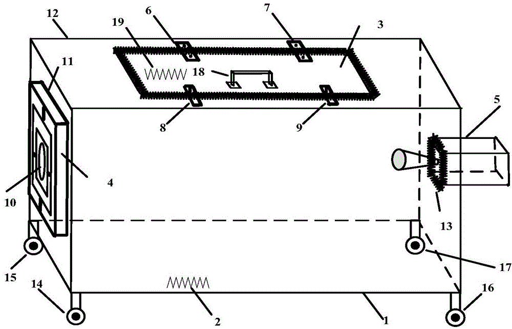
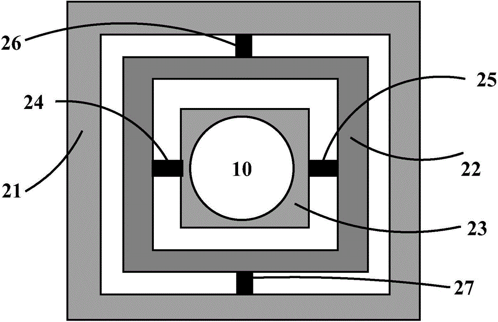
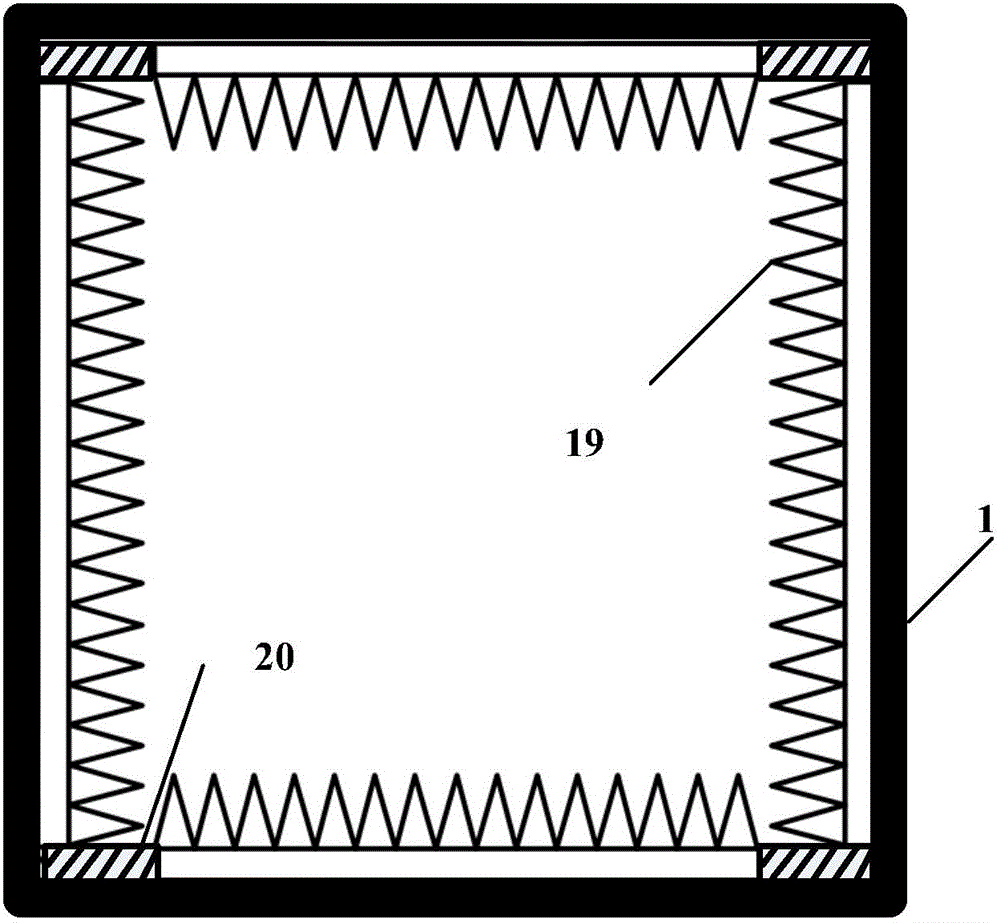
[0021] combine figure 1 , a non-echo isolating box for semi-physical simulation testing of a millimeter-wave radiometer, the non-echo isolating box includes a steel plate outer frame 1, a wave-absorbing material 2, a screen door 3 and a three-frame angle adjustment frame 4; the non-echo The volume of the wave isolation box is 1.4m×0.7m×0.7m.

[0022] The steel plate frame 1 in the non-echo isolation box is a cuboid made of HLS1 type single-layer steel plate, and a first opening 11 and a second opening 13 are opened in the middle of the two faces opposite to each other in the length direction of the cuboid steel plate, and the center of the two openings is Consistent, wherein, the first opening is used to install the three-frame angle adjustment frame 4, and the size is subject to the three-frame angle adjustment frame 4, and the three-frame angle adjustment frame 4 and the first opening are realized by spot welding technology. Seam welding; the second opening 13 is used to in...


PUM

PropertyMeasurementUnit
Thicknessaaaaaaaaaa

Abstract

The invention discloses an echo-free isolation box for testing of a millimeter wave alternating current radiometer. The echo-free isolation box comprises a metal frame and a three-frame inclined angle adjusting frame; the metal frame is a cuboid, wherein an opening is formed in the middle of each of the two opposite surfaces of the cuboid in the length direction, and the three-frame inclined angle adjusting frame and a target simulator are respectively arranged in the two openings; the top surface of the metal frame is provided with an opening which is provided with a shielding door; a wave absorbing material is arranged on the inner side of the metal frame. The echo-free isolation box provides a favorable testing environment for complete machine testing and signal simulation of a projectile-borne millimeter wave alternating current radiometer, also provides a method for measuring an included angle of a terminal sensitive projectile millimeter wave alternating current radiometer, has the advantages of low cost, small size, convenience in use, high performance, good electromagnetic shielding property and the like and is little affected by outside.

Description

technical field [0001] The invention relates to a non-echo isolating box, in particular to a non-echo isolating box used for millimeter-wave AC radiometer testing. Background technique [0002] In the past ten years, with the development of domestic smart munitions and the maturity of millimeter-wave device technology, breakthroughs have been made in the research of millimeter-wave passive detectors (millimeter-wave radiometers), and their costs have been further reduced. The most commonly used detector for sensitive bombs. The millimeter-wave passive detectors in terminal-sensitive bombs are mainly millimeter-wave AC radiometers, which need to be tested and calibrated before they are equipped. The tests include field dynamic tests and static machine performance parameter tests. Static machine performance testing and calibration include sensitivity, integration time, dynamic range testing, etc., as well as simulation and testing of target signals, etc., which can usually be...

Claims


Application Information

Patent Timeline
IPC IPC(8): G01S7/40
CPCG01S7/40
Inventor 许建中彭树生肖泽龙丁勇吴礼王元恺周位强蒋张涛
Owner NANJING UNIV OF SCI & TECH
Learn More