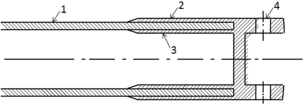
Manufacture method of fiber composite material automobile transmission shaft
A technology of fiber composite materials and drive shafts, which is applied in the field of auto parts manufacturing, can solve the problems of not being able to meet mass production, resin sticking to the mandrel, and difficult demoulding, etc., to meet the requirements of mass production, light weight, The effect of easy demoulding
- Summary
- Abstract
- Description
- Claims
- Application Information
AI Technical Summary
Problems solved by technology
Method used
Image
Examples
example 1
[0033] (1) Prepare an aluminum alloy mandrel with a length of 160cm and an outer diameter of 12cm;
[0034] (2) Polish the aluminum alloy mandrel twice with sandpaper, the first time with 2000 mesh sandpaper, the second time with 4000 mesh sandpaper, and use acetone to clean the polished sleeve three times, with an interval of 10 minutes between each cleaning. Then apply the release agent to the surface of the sleeve twice with an interval of 5 minutes;
[0035] (3) Put the mandrel on the winding machine, lap the fiber tow pre-impregnated with 5222 epoxy resin to the top of the mandrel, and start winding, wherein the first 5cm is the transition zone, and the orientation angle of the fiber tow transitions from 90° to 15°, the orientation angle transitions from 15° to 90° after winding to a distance of 5cm from the other top, and this winding method is kept until the winding thickness is 6mm;
[0036] (4) Wrap two layers of perforated shrinkable isolation film on the wound slee...
example 2
[0042] (1) Prepare an aluminum alloy mandrel with a length of 160cm and an outer diameter of 12cm;
[0043] (2) Polish the aluminum alloy mandrel twice with sandpaper, the first time with 2000 mesh sandpaper, the second time with 4000 mesh sandpaper, and use acetone to clean the polished sleeve three times, with an interval of 10 minutes between each cleaning. Then apply the release agent to the surface of the sleeve twice with an interval of 5 minutes;
[0044] (3) Put the mandrel on the winding machine, lap the fiber tow pre-impregnated with 5222 epoxy resin to the top of the mandrel, and start winding, wherein the first 5cm is the transition zone, and the orientation angle of the fiber tow transitions from 90° to 15°, the orientation angle transitions from 15° to 90° after winding to a distance of 5cm from the other top, and this winding method is kept until the winding thickness is 6mm;
[0045] (4) Wrap two layers of perforated shrinkable isolation film on the wound slee...
example 3
[0051] (1) Prepare an aluminum alloy mandrel with a length of 160cm and an outer diameter of 12cm;
[0052] (2) Polish the aluminum alloy mandrel twice with sandpaper, the first time with 2000-grit sandpaper, the second time with 4000-grit sandpaper, and use acetone to clean the polished sleeve three times, with an interval of 10 minutes between each cleaning. Then apply the release agent to the surface of the sleeve twice with an interval of 5 minutes;
[0053] (3) Put the core mold on the winding machine, lap the fiber tow pre-impregnated with 5222 epoxy resin to the top of the mandrel, and start winding, wherein the first 5cm is the transition zone, and the orientation angle of the fiber tow transitions from 90° to 30°, the orientation angle transitions from 30° to 90° after winding to a distance of 5cm from the other top, and this winding method is maintained until the winding thickness is 6mm;
[0054] (4) Wrap two layers of perforated shrinkable isolation film on the wo...
PUM
| Property | Measurement | Unit |
|---|---|---|
| temperature | aaaaa | aaaaa |
| shear strength | aaaaa | aaaaa |
| thickness | aaaaa | aaaaa |
Abstract
Description
Claims
Application Information
 - R&D Engineer
- R&D Manager
- IP Professional
- Industry Leading Data Capabilities
- Powerful AI technology
- Patent DNA Extraction
Browse by: Latest US Patents, China's latest patents, Technical Efficacy Thesaurus, Application Domain, Technology Topic, Popular Technical Reports.
© 2024 PatSnap. All rights reserved.Legal|Privacy policy|Modern Slavery Act Transparency Statement|Sitemap|About US| Contact US: help@patsnap.com


