Construction Method of Vibrating Squeezing and Expansion Cast-in-situ Pile with Full Casing

A construction method and cast-in-situ pile technology, which is applied in the fields of earthwork drilling, sheet pile walls, foundation structure engineering, etc., can solve the problems of insufficient bearing capacity of the pile body, achieve the improvement of the bearing capacity of the pile body, reduce the amount of concrete used, and reduce the cost Effect

Inactive Publication Date: 2016-11-02
FUJIAN UNIV OF TECH
View PDF8 Cites 0 Cited by
  • Summary
  • Abstract
  • Description
  • Claims
  • Application Information

AI Technical Summary

Problems solved by technology

[0002] Immersed tube cast-in-situ pile is a product of the 1930s. Due to many quality problems of this pile type, it was gradually eliminated after the 1980s and replaced by hammer sinking tube rammed and expanded piles. Although the pile has the advantage of bearing capacity, coupled with the pressure of the rammed tube on the pile top to the concrete inside the tube, it will play a certain role in preventing the pile from breaking and segregating, but because the tube is not pulled out by vibration, the tube is hammered and sunk. Rammed and expanded piles still cannot solve the quality problems of the pile body during construction in coastal soft soil areas, so they have gradually been eliminated after entering the 21st century
[0003] In the prior art, when the project has a large requirement on the bearing capacity of the pile body, the existing cast-in-situ piles have the problem of insufficient bearing capacity of the pile body

Method used


Image

  • Construction Method of Vibrating Squeezing and Expansion Cast-in-situ Pile with Full Casing
  • Construction Method of Vibrating Squeezing and Expansion Cast-in-situ Pile with Full Casing
  • Construction Method of Vibrating Squeezing and Expansion Cast-in-situ Pile with Full Casing

Examples


Embodiment Construction

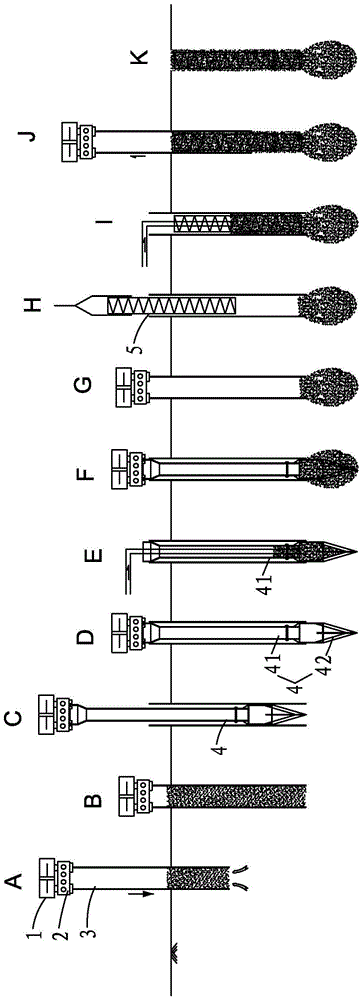
[0023] see Figure 1-3 , a construction method of vibrating extruded and expanded cast-in-place piles with full-casing soil extraction, comprising the following steps:

[0024] A. The steel casing 3 sinks into the soil under the high-frequency vibration of the high-frequency vibrating hammer 1 through the holder 2, and the foundation soil gradually enters the steel casing 3; Stones can be removed by down-the-hole hammer, blasting or manual chiseling.

[0025] B. (2) The steel casing 3 is sunk to the design elevation, and the soil layer in the steel casing 3 is taken mechanically or manually; The equipment is fetched.

[0026] C. Put a special reamer 4 in the steel casing 3;

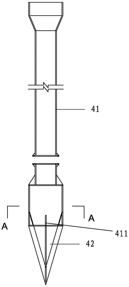
[0027] D. The special reamer 4 is connected to the high-frequency vibratory hammer 1 to carry out vibratory reaming on the inner bottom of the steel casing 3;

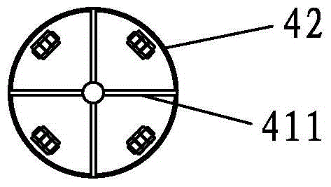
[0028] Described special reamer 4 comprises a tubular body 41 and four flaps 42, and described tubular body 41 is hollow structure, and the a...


PUM


Abstract

A full casing pipe soil taking vibration construction method for a squeezed and expanded cast-in-place pile includes the steps that a steel casing pipe is sunk to the design elevation by a high-frequency vibration hammer through a clamper; soil is taken mechanically or manually; a special hole expander is put in the pipe for vibration hole expansion; concrete is poured into the special hole expander, and vibration hole expansion and concrete pouring are repeatedly performed; a steel reinforcement cage is lifted and put, and concrete is poured into the steel reinforcement cage; the steel casing pipe is pulled out in a vibrating mode to form the squeezed and expanded cast-in-place pile. As the fill concrete is poured while the special hole expander is used for vibration squeezing and expanding, foundation soil of the bottom expanding part can be more compact, a formed expanding head can substantially increase the end resistance of the pile, and the vertical bearing capacity of the pile is improved substantially; when the same vertical load is borne by a single pile, the needed pile length is small, the usage amount of the concrete is small, and the foundation project cost can be substantially reduced.

Description

technical field [0001] The invention belongs to the field of engineering construction, and in particular relates to a construction method of full-sleeved soil-taking vibration squeezed and expanded cast-in-situ piles. Background technique [0002] Immersed tube cast-in-situ pile is a product of the 1930s. Due to many quality problems of this pile type, it was gradually eliminated after the 1980s and replaced by hammer sinking tube rammed and expanded piles. Although the pile has the advantage of bearing capacity, coupled with the pressure of the rammed tube on the pile top to the concrete inside the tube, it will play a certain role in preventing the pile from breaking and segregating, but because the tube is not pulled out by vibration, the tube is hammered and sunk. Rammed and expanded piles still cannot solve the problem of pile body quality when they are constructed in coastal soft soil areas, so they have gradually been eliminated after entering the 21st century. [00...

Claims


Application Information

Patent Timeline
Patent Type & Authority Patents(China)
IPC IPC(8): E02D5/44E02D9/02E21B10/32
CPCE02D5/44E02D9/02E21B10/32
Inventor 简洪钰林海
Owner FUJIAN UNIV OF TECH
Why Eureka
Try Eureka