
Stepping chip removing device

A chip removal device and step-by-step technology, applied in the field of step-by-step chip removal devices, can solve the problems of low chip removal efficiency and stuck waste, and achieve the effect of high chip removal efficiency and fast speed.

Inactive Publication Date: 2015-05-20
TIANJIN MAIKE TECH DEV
View PDF0 Cites 7 Cited by
  • Summary
  • Abstract
  • Description
  • Claims
  • Application Information

AI Technical Summary

Problems solved by technology

[0002] In the process of machining semi-finished products by machine tools, lathes are used to process them, especially in the process of processing large steel parts, etc., there will be long strips, rolls, and lumps of waste. For the discharge of such waste Generally, the stepping chip removal device is preferred. However, when the existing stepping chip removal device performs chip removal, it relies on the push rod to reciprocate the chip removal box, and then pushes the waste material to the discharge port. This method exists The efficiency of chip removal is low, and the problem of waste material jamming occurs due to large waste materials during the chip removal process

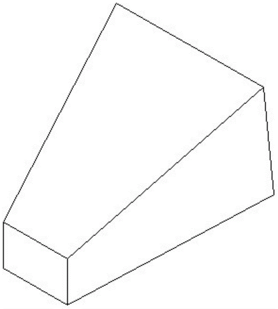
Method used


Image

  • Stepping chip removing device
  • Stepping chip removing device

Examples


Embodiment Construction

[0012] Specific embodiments of the present invention are described below in conjunction with accompanying drawing:

[0013] Such as Figure 1-2 As shown, the step-by-step chip removal device includes a chip removal box 1 that supports the entire device, and a number of barbs 2 are provided on the side walls on both sides of the device, and several chip removal boxes are placed in the middle of the chip removal box 1 4. Every two chip removal boxes 3 are connected by a connecting shaft 5, and the outermost connecting shaft 5 is connected to a hydraulic cylinder 3 through a connecting piece 6, wherein: an electromagnet 41 is arranged in the chip removal box 4, and then the When energized, the waste materials (such as strips, lumps, and rolls) in the chip removal box 1 can be adsorbed on the chip removal box 4. The electromagnet 41 is connected to the control system through the wires in the shaft 5. connect.

[0014] The chip removal box 4 is a conical block, and its large end ...


PUM


Abstract

The invention provides a stepping chip removing device. The stepping chip removing device comprises a chip removing case, a plurality of barbs, a plurality of chip removing boxes and a hydraulic cylinder, wherein the barbs are arranged on the two sidewalls of the chip removing case, the chip removing boxes are movably arranged in the middle of the chip removing case and connected through connecting shafts, and the hydraulic cylinder is connected with the connecting shaft at the foremost end. A connecting piece is arranged between the hydraulic cylinder and the connecting shaft at the foremost end. An electromagnet is arranged in each chip removing box. The stepping chip removing device has the advantages that when the hydraulic cylinder conducts pushing, the electromagnets are powered on, and scraps can be attracted to the chip removing boxes to the maximum extent and conveyed; when the hydraulic oil retracts, the electromagnets are powered off, the chip removing boxes can hardly take the pushed scraps back when retracting, and the scraps will not get stuck; the stepping chip removing device has the advantages of high chip removing efficiency and high speed.

Description

technical field [0001] The invention relates to the field of iron scrap removal equipment, in particular to a step-by-step chip removal device. Background technique [0002] In the process of machining semi-finished products by machine tools, lathes are used to process them, especially in the process of processing large steel parts, etc., there will be long strips, rolls, and lumps of waste. For the discharge of such waste Generally, the stepping chip removal device is preferred. However, when the existing stepping chip removal device performs chip removal, it relies on the push rod to reciprocate the chip removal box, and then pushes the waste material to the discharge port. This method exists The chip removal efficiency is low, and the waste material is stuck due to the large waste material during the chip removal process. Contents of the invention [0003] The problem to be solved by the present invention is to provide a step-by-step chip removal device, which can quic...

Claims


Application Information

Patent Timeline
Patent Type & Authority Applications(China)
IPC IPC(8): B65G25/02
Inventor 于保民
Owner TIANJIN MAIKE TECH DEV
Learn More