
Method for machining deep hole

A deep hole and processing drilling technology, which is applied in the direction of metal processing equipment, manufacturing tools, boring/drilling, etc., can solve the problems of deep hole position deviation, uneven size, drill bit vibration, etc.

Inactive Publication Date: 2015-05-20
HARBIN
View PDF5 Cites 10 Cited by
  • Summary
  • Abstract
  • Description
  • Claims
  • Application Information

AI Technical Summary

Problems solved by technology

[0002] In mechanical processing, it is often encountered that deep holes need to be drilled on the product. During the processing process, due to the deep hole, the length of the drill bit is long, and the deflection is serious. The position of the hole is deviated, the size is uneven, and sometimes the drill bit breaks off

Method used


Image

  • Method for machining deep hole

Examples


Embodiment Construction

[0010] The technical solution of the present invention will be described in further detail below in conjunction with accompanying drawing and embodiment:

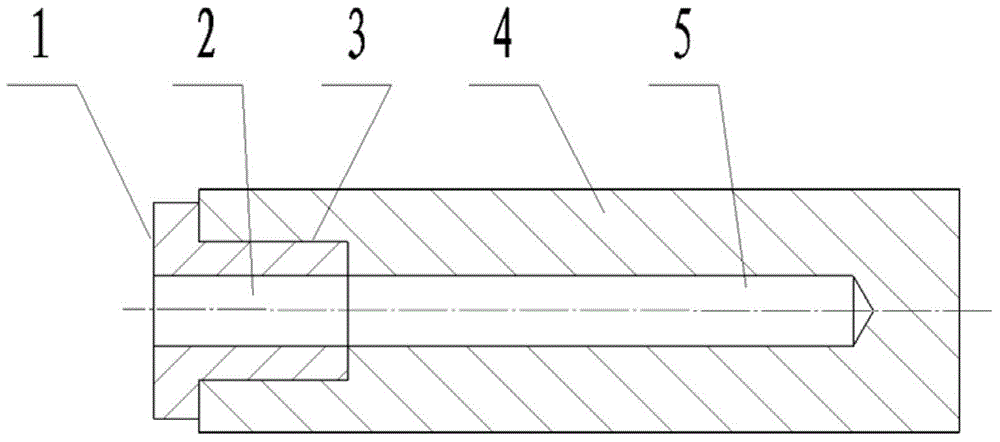
[0011] See attached figure 1 As shown, the method for processing deep holes is characterized in that: the steps of the method are:

[0012] The first step is to process the drill sleeve hole, and the drill sleeve hole 3 is processed at the center position of the part 4 to be processed where the deep hole 5 needs to be processed;

[0013] The second step is to insert a drill sleeve, add a drill sleeve 1 and install it in the drill sleeve hole 3, the diameter of the central hole 2 of the drill sleeve 1 is the same as that of the deep hole 5;

[0014] The 3rd step, drill deep hole, drill deep hole 5 to required depth by the center hole 2 of drill bushing 1 with the extension drill bit.

[0015] Compared with the prior art, the technical solution of the present invention has a certain guide and fixation effect on the drill bi...


PUM


Abstract

The invention provides a method for machining a deep hole. The method includes the steps that firstly, a drill bushing hole is machined, wherein the drill bushing hole 3 is machined in the center of the deep hole 5 needing to be machined in a part 4 to be machined; secondly, a drill bushing is inserted, wherein the drill bushing 1 is additionally arranged and installed in the drill bushing hole 3, and the center hole 2 of the drill bushing 1 and the deep hole 5 are the same in diameter; thirdly, the deep hole is drilled, wherein a lengthened drill bit passes the center hole 2 of the drill bushing 1 to drill the deep hole 5 into required depth. By the adoption of the technical scheme, compared with the prior art, the drill bushing generates certain guiding and fixing effects on the drill bit, the phenomenon that the drill bit vibrates is effectively controlled, the requirement for the machining depth is met, the requirements for the location degree and the roundness of the machined hole are met, and the drill bit is prevented from being broken off.

Description

technical field [0001] The invention relates to a method for processing deep holes, which belongs to the technical field of mechanical processing. Background technique [0002] In mechanical processing, it is often encountered that deep holes need to be drilled on the product. During the processing process, due to the deep hole, the length of the drill bit is long, and the deflection is serious. The drill bit often vibrates due to inaccurate positioning, which makes the deep The hole position is deviated, the size is uneven, and sometimes the drill bit breaks. Contents of the invention [0003] The present invention is designed to provide a method for processing deep holes aiming at the deficiencies in the above-mentioned prior art. Its purpose is to use the drill sleeve to guide and fix the drill bit to a certain extent, so that the vibration of the drill bit can be effectively controlled. The position accuracy and roundness requirements of the processed holes are guaran...

Claims


Application Information

Patent Timeline
IPC IPC(8): B23B35/00B23B41/02B23B49/02
CPCB23B35/00B23B41/02B23B49/02
Inventor 宋斌李广伟于四龙王龙陈永健
Owner HARBIN
Learn More