
Air-conditioner and control method thereof

A control method and technology for an air conditioner, which are applied in the directions of control input involving air characteristics, space heating and ventilation control input, heating and ventilation control systems, etc. The suction volume and resistance are consistent, and the effect of solving the problem of difficulty in controlling the suction volume of the refrigerant

Active Publication Date: 2015-05-13
GREE ELECTRIC APPLIANCES INC
View PDF6 Cites 8 Cited by
  • Summary
  • Abstract
  • Description
  • Claims
  • Application Information

AI Technical Summary

Problems solved by technology

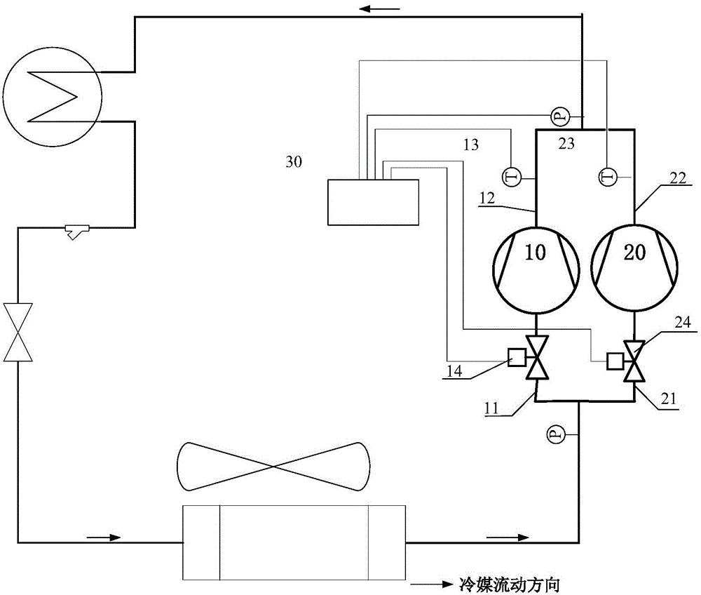
[0004] The main purpose of the present invention is to provide an air conditioner and its control method to solve the problem in the prior art that the amount of refrigerant sucked by each compressor in the parallel compressor unit of the air conditioner is difficult to control

Method used


Image

  • Air-conditioner and control method thereof
  • Air-conditioner and control method thereof
  • Air-conditioner and control method thereof

Examples


Embodiment 2

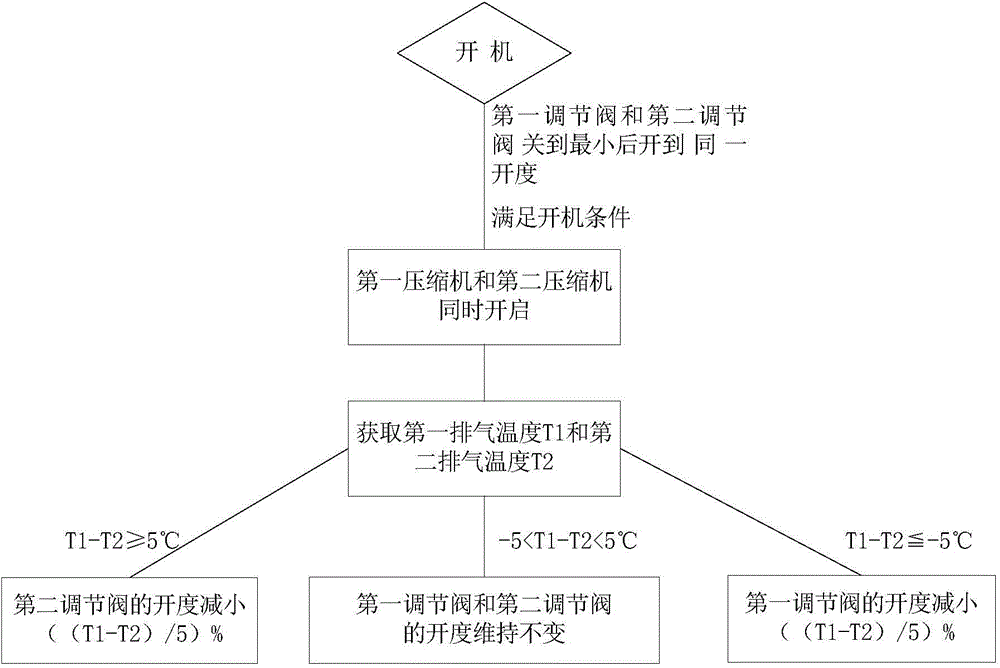
[0044] The difference between the second embodiment and the first embodiment is that when the difference between the first exhaust temperature and the second exhaust temperature is not within the range of the first preset value and the second preset value, the first regulating valve 14 and the second The control modes of the two regulating valves 24 are different, such as image 3 Shown:

[0045] When the first exhaust temperature is greater than the second exhaust temperature, and the difference between the first exhaust temperature and the second exhaust temperature is greater than the first preset value, keep the opening of the second regulating valve 24 unchanged, and increase the A degree of opening of the regulating valve 14 . Specifically, increasing the opening degree of the first regulating valve 14 can reduce the resistance in the first suction pipe 11 . Since the first compressor 10 and the second compressor 20 are arranged in parallel, if the resistance in the se...

Embodiment 3

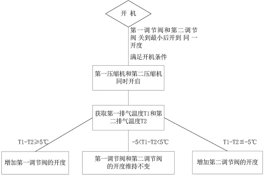
[0048] The difference between the third embodiment and other embodiments is that when the difference between the first exhaust temperature and the second exhaust temperature is not within the range of the first preset value and the second preset value, the first regulating valve 14 and the second The control modes of the two regulating valves 24 are different, such as Figure 4 Shown:

[0049] When the first exhaust temperature is greater than the second exhaust temperature, and the difference between the first exhaust temperature and the second exhaust temperature is greater than the first preset value, increase the opening degree of the first regulating valve 14 and decrease the first Second, adjust the opening degree of the valve 24 , specifically, the above operation makes the resistance in the first suction pipe 11 increase while reducing the resistance in the second suction pipe 21 . Since the first compressor 10 and the second compressor 20 are arranged in parallel, wh...


PUM


Abstract

The invention provides an air-conditioner and a control method thereof. The air-conditioner comprises a first compressor and a second compressor which are arranged in parallel. The air-conditioner further comprises a first air suction pipe, a first air exhaust pipe, a second air suction pipe and a second air exhaust pipe, wherein the first air suction pipe and the first air exhaust pipe are connected to the first compressor, and the second air suction pipe and the second air exhaust pipe are connected to the second compressor. The air-conditioner further comprises a first temperature sensor, a second temperature sensor, a first regulating valve and a second regulating valve. The first temperature sensor is arranged on the first air exhaust pipe and used for acquiring the first air exhaust temperature of the first compressor, and the second temperature sensor is arranged on the second air exhaust pipe and used for acquiring the second air exhaust temperature of the second compressor. The first regulating valve is used for controlling the refrigerant suction volume of the first compressor, the second regulating valve is used for controlling the refrigerant suction volume of the second compressor, and the opening degree of the first regulating valve and / or the opening degree of the second regulating valve are / is determined through the difference value of the first air exhaust temperature and the second air exhaust temperature. According to the technical scheme, the problem that the refrigerant suction volumes of all the compressors in a parallel connection compressor set in an air-conditioner cannot be controlled easily in the prior art is effectively solved.

Description

technical field [0001] The present invention relates to the technical field of air conditioners, in particular to an air conditioner and a control method thereof. Background technique [0002] In light-duty commercial air-conditioning units, due to the comprehensive consideration of the characteristics of the scroll compressor and the scope of use, 10-hp and 12-hp compressors are the most commonly used and the most cost-effective. Therefore, when the required cooling capacity of the compressor unit reaches 60 hp, 70 hp or even greater, in order not to cause a large number of control components due to too many systems, generally a single system will use two 10-hp or 12-hp compressors machines in parallel. However, while using parallel compressor units to improve the cost performance, the pressure ratio of the units may be too high, too low or the refrigerant injection is too large. Excessive refrigerant injection can easily lead to an unbalanced phenomenon in which the devi...

Claims


Application Information

Patent Timeline
Patent Type & Authority Applications(China)
IPC IPC(8): F24F11/02
CPCF24F11/30F24F11/62F24F11/64F24F11/83F24F11/84F24F11/89F24F2110/00
Inventor 黄章义陈培生徐美俊唐育辉石伟刘鸣
Owner GREE ELECTRIC APPLIANCES INC
Learn More