An unloadable elastic support device and a method for temporarily supporting loads using it

An elastic support device and elastic support technology, which is applied in the field preparation of pillars and building components, construction, etc., can solve the problems of unrestricted support force, high maintenance cost, poor safety, etc., and achieve simple structure, no damage to the structure, easy-to-handle effects

Active Publication Date: 2016-10-05
SHANGHAI MECHANIZED CONSTR GRP
View PDF8 Cites 0 Cited by
  • Summary
  • Abstract
  • Description
  • Claims
  • Application Information

AI Technical Summary

Problems solved by technology

[0004] Aiming at the problems that conventional rigid temporary support members cannot limit the support force and have poor safety when unloading, and use hydraulic jacks as supports, the operation is complicated and the maintenance cost is high. The purpose of this invention is to provide an unloadable elastic support device and its The method of supporting the load, using the support device installed with the butterfly spring group to transfer the load of the upper structure, control the load of the temporary support, protect the safety of the underground building structure below it, and remove the support device through the method of sand leakage, and unload the load to permanent structure

Method used


Image

  • An unloadable elastic support device and a method for temporarily supporting loads using it
  • An unloadable elastic support device and a method for temporarily supporting loads using it

Examples


Embodiment 1

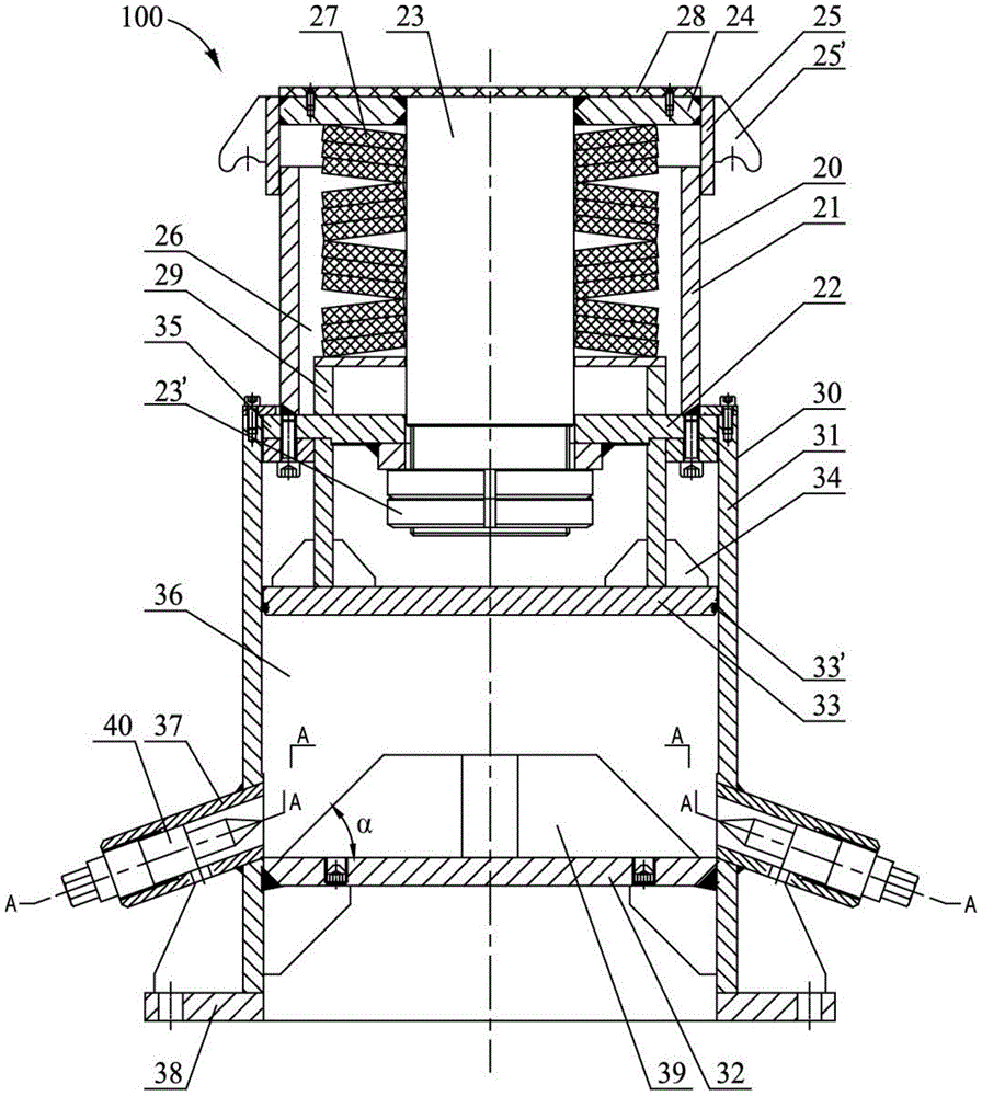
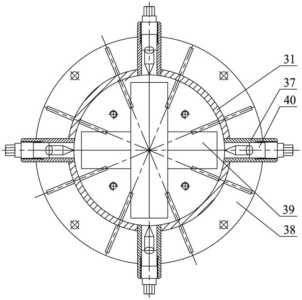
[0027] Example 1: Combining figure 1 and figure 2 Describe the unloadable elastic support device 100 of the present invention, which includes an elastic bracket 20 and an unloading assembly 30 arranged from top to bottom, wherein the elastic bracket 20 is sleeved in the unloading assembly 30 and can be longitudinally arranged along the inner wall of the unloading assembly 30 relative sliding;

[0028] The elastic bracket 20 includes an inner sleeve 21 , a bottom plate 22 fixed on the bottom of the inner sleeve 21 , a mandrel 23 vertically arranged in the inner sleeve 21 , and an upper cover plate fixed on the top of the mandrel 23 . The bottom end of the mandrel 23 passes through the central hole of the bottom plate 22 and is locked by a nut 23 ′. The upper cover plate is formed by connecting the end plate 24 and the outer sleeve 25 , and the outer sleeve 25 is sleeved outside the inner sleeve 21 and can slide relatively along the longitudinal direction of the inner sleeve ...

Embodiment 2

[0039] Embodiment 2: Combination figure 1 and figure 2 Illustrate the method of utilizing the unloadable elastic support device of the present invention to temporarily support loads, and the specific steps are as follows:

[0040] S101: first calculate and determine the maximum load and maximum displacement of the support node, determine the specification, quantity and superimposition mode of the butterfly spring according to the support stiffness, bearing capacity and deformation required by the design, assemble the unloadable elastic support device 100, pass through the sand cylinder 31 Bolt holes 32' on the bottom cover plate 32 are filled with sand bodies into cavity 2 36, and are tightened with bulkhead bolts to close the above bolt holes, and then the disc spring group 27 is pre-compressed and tightened at the bottom of the mandrel 23. Nut 23', the purpose of pre-compressing the disc spring group 27 is to allow the disc spring group 27 to enter the working state (it is...


PUM


Abstract

The invention relates to the technical field of constructional engineering construction, and discloses an elastic supporting device capable of performing unloading and a temporary load supporting method with the elastic supporting device to solve the problems that a common rigidity temporary supporting component cannot limit supporting force, safety is poor during unloading, a hydraulic jack is adopted as a support, operation is complex, and the maintaining cost is high. The elastic supporting device comprises an unloading assembly and an elastic support which is arranged in the unloading assembly in a sleeved mode and longitudinally slides along the inner wall, a core shaft is arranged in an inner sleeve, the bottom end of the core shaft penetrates through a bottom plate and is locked through a nut, the top end of the core shaft is connected with an upper cover plate, the core shaft is sleeved with a belleville spring set, and an outer sleeve is arranged outside the inner sleeve in a sleeving mode and can longitudinally slide along the inner sleeve. The unloading assembly comprises a sand cylinder with the bottom connected with a bottom sealing plate, and a partition plate arranged in the sand cylinder, the bottom plate and the partition plate are matched with the sand cylinder in internal diameter and can longitudinally move along the inner wall of the sand cylinder, a second cavity of the sand cylinder is filled with sand, a sand discharging pipe is arranged at the lower portion of the sand cylinder, a sealing bolt of the sand discharging pipe is loosened during unloading, the sand in the second cavity is discharged, the height of the supporting device is reduced, and the unloading purpose is achieved.

Description

technical field [0001] The invention relates to the technical field of civil engineering construction, in particular to an unloadable elastic support device and a method for temporarily supporting loads by using the same. Background technique [0002] Building steel structures, especially long-span steel structures, often use steel pipe members to temporarily support the upper steel structure during construction. After the upper steel structure is formed as a whole, the steel pipes are cut off by gas cutting to reduce the original height, so as to achieve the purpose of unloading. These temporary support members are then removed. During the construction process, the force transmitted from the upper steel structure to these temporary support members is very large, and this unloading method is not safe at the same time. When building long-span steel structures above subways or other underground structures, excessive forces on temporary support members may affect the safety of...

Claims


Application Information

Patent Timeline
Patent Type & Authority Patents(China)
IPC IPC(8): E04G25/04
Inventor 周锋郑祥杰吴金山吴欣之李璐郁政华孙继辉毕伟麟
Owner SHANGHAI MECHANIZED CONSTR GRP
Why Eureka
Try Eureka