
A tiltable trailer

A tilting and trailering technology, applied in the field of trailers, can solve the problems of limited length, unfavorable vehicle up and down, and large slope angle, etc., to achieve the effect of controllable tilt angle, convenient operation and obvious effect

Active Publication Date: 2018-04-13
遵义梅花汽车科技发展有限公司
View PDF7 Cites 0 Cited by
  • Summary
  • Abstract
  • Description
  • Claims
  • Application Information

AI Technical Summary

Problems solved by technology

[0002] At present, in order to improve transportation efficiency, trailers are widely used as supplementary equipment on various vehicles. Among them, the main methods of loading and unloading goods on trailers are as follows: (1) General goods are carried manually. For large goods, before transportation, use The crane loads the goods, and unloads them with a crane after arriving at the destination; (2) There is a springboard at the tail of the trailer. Driving on the trailer, but due to the limited length of the springboard, the slope angle formed is relatively large, which is not conducive to the up and down of the vehicle, especially when switching from the springboard to the platform, it is especially unfavorable for vehicle loading and unloading; (3) For small road rescue vehicles , in order to load the immobile vehicle on the rescue vehicle, usually the platform of the rescue vehicle is directly tilted backward under the action of the hydraulic cylinder, and the rear end touches the ground to form a slope, so that the vehicle to be rescued can be loaded on the rescue vehicle, but because the flat panel It is the overall tilt and the axle is close to the rear of the vehicle, resulting in a relatively large slope angle, which is the same as the above method (2), and this method is also not conducive to the loading and unloading of the rescued vehicle

Method used


Image

  • A tiltable trailer
  • A tiltable trailer

Examples


Embodiment Construction

[0014] The invention will be described in further detail below in conjunction with the accompanying drawings and specific embodiments.

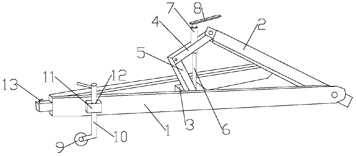
[0015] combine figure 1 with figure 2 As shown, a tiltable trailer of the present invention includes a drag plate 14 and a traction device, and the traction device includes a first traction frame and a second traction frame, and the rear end of the first traction frame is connected to the second traction frame. The rear end of the second traction frame is hinged, and the rear end of the second traction frame is affixed to the front end of the carriage 14. At least one group of running wheels 15 are provided at the bottom of the carriage, wherein the first traction frame is larger than the second traction frame. In this embodiment The first traction frame and the second traction frame are V-shaped structures, and the traction frames can also be arranged in a wedge shape or other shapes, and the open end of the V-shaped structure is the rear ...


PUM


Abstract

A trailer capable of being inclined comprises a trailing plate, a traction device, a foldable connecting piece and a lifting device. The traction device comprises a first traction frame and a second traction frame, the first traction frame is larger than the second traction frame, the rear end of the first traction frame and the front end of the second traction frame are hinged, and the rear end of the second traction frame is fixedly connected with the front end of the trailing plate. The foldable connecting piece is connected with the front end of the first traction frame and the front end of the second traction frame. One end of the lifting device acts on the first traction frame, the other end of the lifting device is connected with the foldable connecting piece, and the foldable connecting piece is controlled by the lifting device to drive the front end of the second traction frame to get close to or away from a beam. At least one set of traveling wheels is arranged at the bottom of the trailing plate. The two traction frames are controlled by the lifting device to form an included angle within a certain range, so that the trailing plate is inclined to a certain degree, the trailer is simple in structure, convenient to operate and obvious in effect, and the inclination angle is controllable.

Description

technical field [0001] The present invention relates to a trailer. Background technique [0002] At present, in order to improve transportation efficiency, trailers are widely used as supplementary equipment on various vehicles. Among them, the main methods of loading and unloading goods on trailers are as follows: (1) General goods are carried manually. For large goods, before transportation, use The crane loads the goods, and unloads them with a crane after arriving at the destination; (2) There is a springboard at the tail of the trailer. Driving on the trailer, but due to the limited length of the springboard, the slope angle formed is relatively large, which is not conducive to the up and down of the vehicle, especially when switching from the springboard to the platform, it is especially unfavorable for vehicle loading and unloading; (3) For small road rescue vehicles , in order to load the immobile vehicle on the rescue vehicle, usually the platform of the rescue veh...

Claims


Application Information

Patent Timeline
Patent Type & Authority Patents(China)
IPC IPC(8): B62D59/02
CPCB62D59/02
Inventor 江志欢张君伟李文斌邱和平李一飞
Owner 遵义梅花汽车科技发展有限公司
Learn More