Emergency power supply circuit and power supply circuit conversion method
An emergency power supply and line technology, applied in emergency power supply arrangements, circuit devices, electrical components, etc., can solve problems such as high cost, many fault points, and large losses
- Summary
- Abstract
- Description
- Claims
- Application Information
AI Technical Summary
Problems solved by technology
Method used
Image

Examples
Embodiment 1
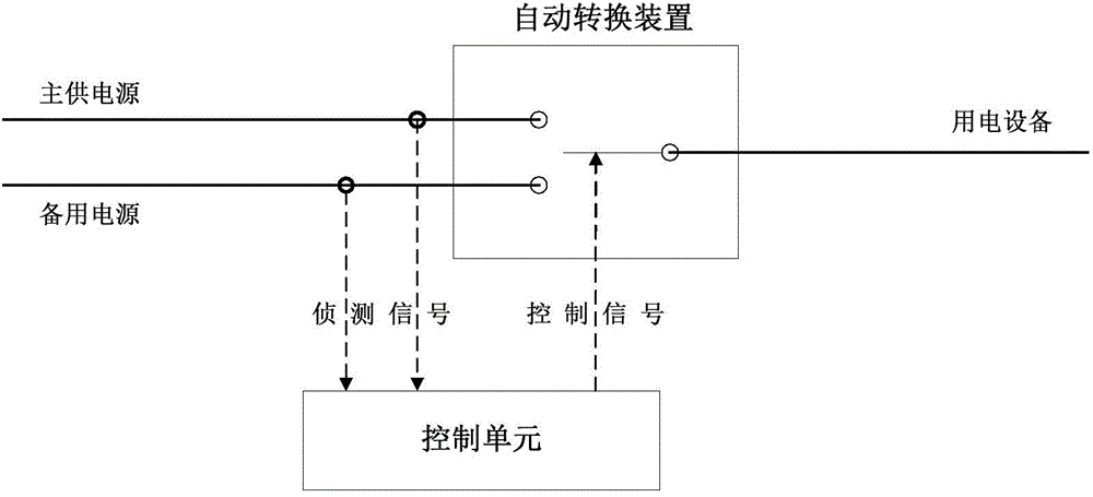
[0035] refer to figure 1 As shown, an emergency power supply circuit includes a main power supply line (main power supply), a backup power supply line (backup power supply), and a dual-way automatic conversion device connected to the main power supply line and the backup power supply line. The automatic conversion device is connected with the electrical equipment, and the two-way automatic conversion device is connected with the control unit, and the control unit performs real-time sampling and detection on the instantaneous voltage value and phase of the input voltage of the main power supply line to obtain a detection Measure the signal, and calculate the sending time of the control signal according to the action time characteristics of the two-way automatic switching device, so that the action time point of the two-way automatic switching device is consistent with the time when the input voltage value of the main power supply line reaches zero. During the power supply proce...
Embodiment 2
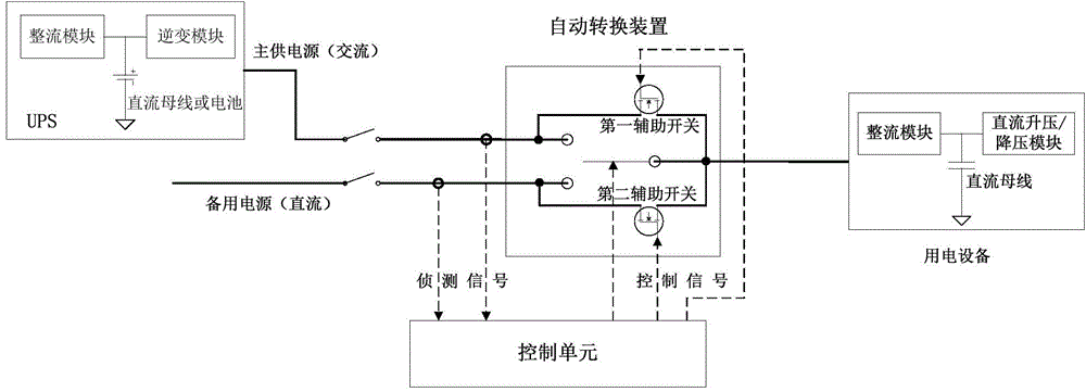
[0039] refer to figure 2As shown, in this embodiment, after canceling the inverter module in the backup power supply line, the DC power supply is directly provided to the electrical equipment for backup, reducing the inverter link to reduce losses and equipment failure points to reduce equipment costs. Switching between the main and standby power supply lines prevents the situation that the DC power cannot be cut off during the switching process from the backup to the main power supply line, and further prevents the process of switching from the main to the standby when the method described in Embodiment 1 fails, adding a A switching scheme, a first auxiliary switch connected in parallel with the two-way automatic conversion device is provided between the main power supply line (main power supply) and the electrical equipment, and the first auxiliary switch adopts semiconductor switching components , the first auxiliary switch is electrically connected to the control unit and...
Embodiment 3
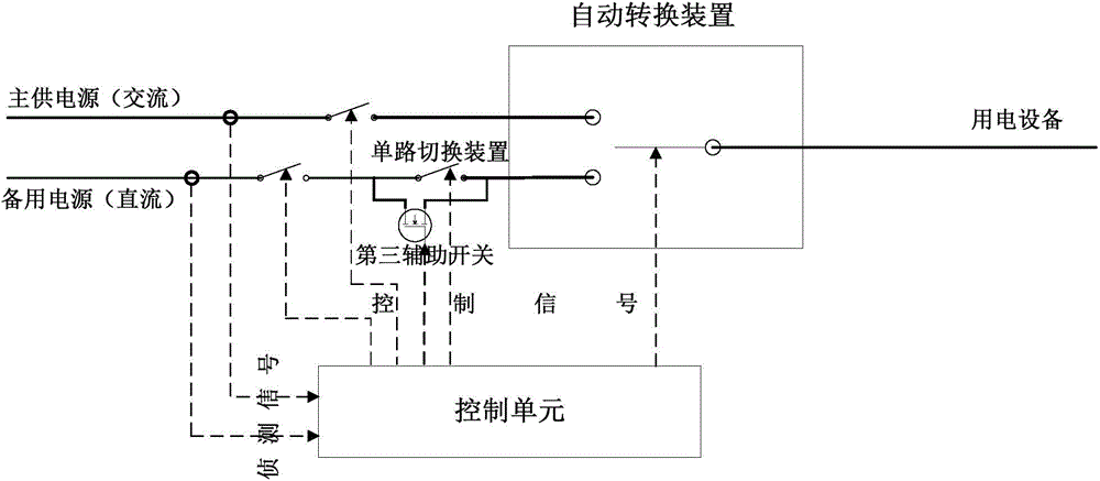
[0043] Please refer to image 3 As shown, the emergency power supply circuit provided by this embodiment is different from that of Embodiment 2. In this embodiment, a second auxiliary switch is not connected in parallel to the dual-way automatic transfer device, but a second auxiliary switch is provided on the backup power supply line. There is a single-way switching device, the backup power supply line is provided with a third auxiliary switch connected in parallel with the single-way switching device, the third auxiliary switch adopts semiconductor switching components, and the third auxiliary switch is connected with the control unit connection. The third auxiliary switch adopts IGBT or MosFET semiconductor switching components. Separate switches are provided at the starting ends of the main power supply line (main power supply) and the standby power supply line (backup power supply). The specific steps to convert the operation method are,
[0044] When the main power su...
PUM
 Abstract
Description
Claims
Application Information
 - Generate Ideas
- Intellectual Property
- Life Sciences
- Materials
- Tech Scout
- Unparalleled Data Quality
- Higher Quality Content
- 60% Fewer Hallucinations
Browse by: Latest US Patents, China's latest patents, Technical Efficacy Thesaurus, Application Domain, Technology Topic, Popular Technical Reports.
© 2025 PatSnap. All rights reserved.Legal|Privacy policy|Modern Slavery Act Transparency Statement|Sitemap|About US| Contact US: help@patsnap.com