
an electric bullet

A bullet and electro-acupuncture technology, applied in warheads, ammunition, weapon accessories, etc., can solve problems such as injury to life and loss of resistance, and achieve the effect of easy equipment and reduced damage

Active Publication Date: 2016-04-06
SOUTHWEST UNIV
View PDF5 Cites 0 Cited by
  • Summary
  • Abstract
  • Description
  • Claims
  • Application Information

AI Technical Summary

Problems solved by technology

But ordinary pistol bullets are likely to hurt lives, so there is an urgent need for a non-lethal weapon that can be used to subdue criminal suspects or wound mad cows, so that the target loses the ability to resist instantly

Method used


Image

  • an electric bullet
  • an electric bullet
  • an electric bullet

Examples


Embodiment Construction

[0010] The present invention will be further described in detail below in conjunction with the accompanying drawings and examples. The following examples are only used to explain the present invention, and do not constitute a limitation to the protection scope of the present invention.

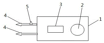
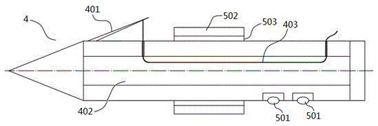
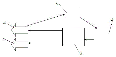
[0011] Such as figure 1 , figure 2 , image 3 The electric shock bullet shown includes a casing 1, a battery 2 and a pulse high voltage generator 3 arranged in the casing 1, and the model of the pulse high voltage generator in this embodiment is MC500-wx1.

[0012] The front end of the housing 1 is provided with two metal electric needles 4 respectively connected to the output ends of the pulse high voltage generator 3, and a switch 5 is arranged on one of the electric needles, and the switch 5 includes a Two metal contacts 501 on the rear surface of the electric needle and a control ring 502 slidably sleeved on the electric needle. The metal contact is insulated from the electric needle a...


PUM


Abstract

The invention discloses an electric-shock bullet. The electric-shock bullet comprises a shell, a battery arranged in the shell and a high-voltage pulse generator. Two electric needles which are connected with the output end of the high-voltage pulse generator are arranged on the front end of the shell. The electric-shock bullet can subdue a suspect non-fatally and rapidly.

Description

technical field [0001] The invention relates to a non-lethal electric shock bullet for police use. Background technique [0002] In the process of carrying out the tasks of public security and civilian police, in many cases, it is hoped that the suspect can be quickly subdued instead of fatal. But general pistol bullets are likely to injure lives, so there is an urgent need for a non-lethal weapon that can be used to subdue criminal suspects or wound mad cows, so that the target loses the ability to resist instantly. Contents of the invention [0003] The object of the present invention is to provide an electric shock bullet, which can be fired by existing firearms and can effectively subdue criminal suspects. [0004] The electric shock bullet according to the present invention includes a casing, a battery and a pulse high voltage generator arranged in the casing, and two metal electric needles respectively connected to the output ends of the pulse high voltage generator...

Claims


Application Information

Patent Timeline
Patent Type & Authority Patents(China)
IPC IPC(8): F42B30/02
Inventor 孙卫伟
Owner SOUTHWEST UNIV
Learn More